Ultrasonic machining is a process of manufacturing that removes material from the surface through high frequency, low amplitude vibrations of a tool against the material surface, presence of fine abrasive particles.
In this paper, we will study the Definition, Construction or Parts, Working Principles, Advantages, Disadvantages, and Application of Ultrasonic Machining in detail.
Note: At the end of the article you can download whole article in PDF format.
What is Ultrasonic Machining Process?
Ultrasonic machining is a non-conventional machining process in which the abrasives hits on the workpiece to remove the material. This method of machining resorts to percussion or hammering of abrasives against the workpiece with the tool.
So, we have a tool, it is not directly impacting the workpiece, but there are some abrasive particles put in between the workpiece and the tool.
These abrasive particles are hard and they are they can retain their shape which means they are rigid therefore, they can cause impact erosion of the workpiece material when working in this particular mode of percussion.
So, hammering is done by a body which is known as a tool. The tool material has been sufficiently ductile so that in itself does not undergo brittle fracture.
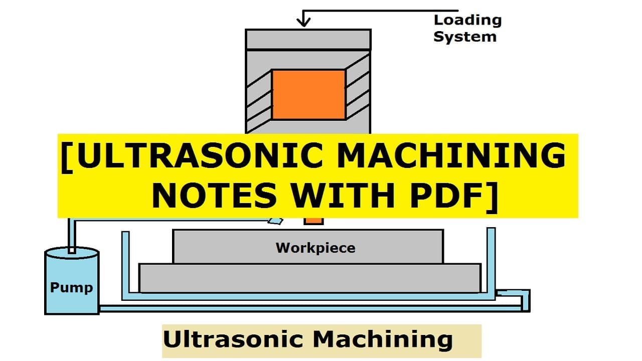
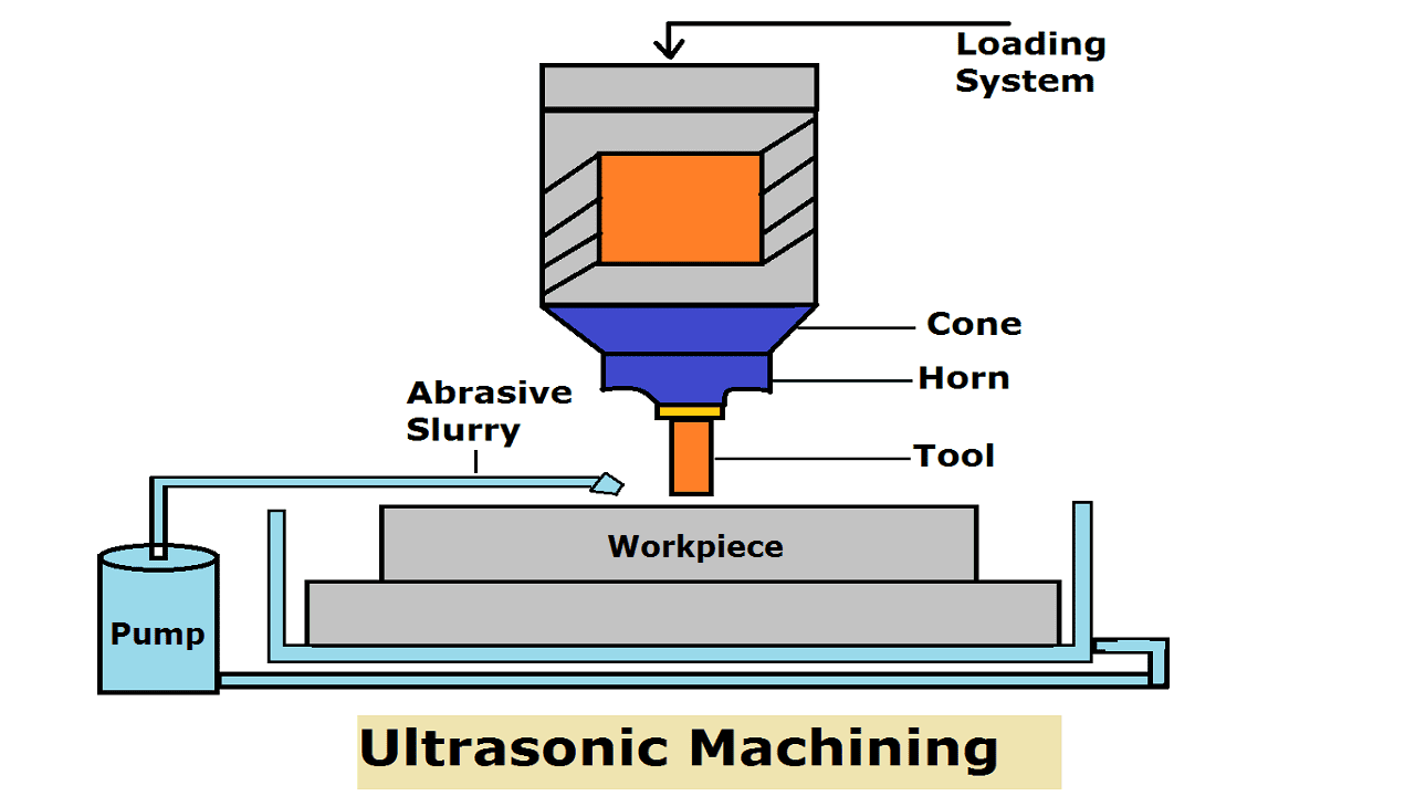
Ultrasonic Machining Process Construction or Parts:
Ultrasonic Machining consists of the following main parts:
- Power Supply
- Velocity Transformer
- Tool
- Abrasive Slurry
- Electro-mechanical transducer
- Abrasive gun
- Workpiece
Power Supply:
The power supply is also called a high-frequency generator or electronic oscillator. The main function is to convert a normal electrical supply that has a frequency range of 50-60 HZ to a high-frequency electrical supply up to range 20-40kHZ but the amplitude of the vibration will be small up to a range of microns
Velocity Transformer:
Velocity transformer is also called the design of the horn. The function of the horn is to amplify and focus the vibration of the transducer to an adequate intensity for driving the tool to fulfill the cutting operation.
They are made of hard, non-magnetic, and easily machinable steel having good fatigue strength like K-Monel, Metal bronze, and Mild steel.
Linearly tapered and exponentially taped horns have lengths equal to one-half of the wavelength of sound in the metal of which they are made.
Tool:
Hammering is done by a body that is known as the tool and the tool material has been sufficiently ductile so that in itself does not undergo brittle fracture.
However, we can not avoid the removal of material from the tool parallel with the workpiece, so tool wear is of sufficient degree and it should also be fatigue resistant because in order to increase the material removal rate we are increasing the hammering rate to ultrasonic frequencies.
So, if that be so, there will be dynamic loading on the tool material. So, it should be fatigue resistant. And the rate of machining is proportional to this hammering
Abrasive Slurry:
Abrasives need to be applied at the site of machining and need to be removed together with machined material from workpiece and tool material, so they are carried in a slurry to and from the site of machining.
The tool is pressed against the workpiece to create a slight pressure, low enough so as not to crush abrasives and high enough so as to ensure fracturing of the workplace.
Abrasives have higher fracture strength than the workpiece. first of all, abrasives have to be supplied.
So, they are applied at the machining site by being carried in in a water medium generally and it is called a slurry.
For Example: Say you put volume per volume say 20 parts of abrasives in 100 parts of water and let it be applied by a nozzle that means, by a jet at the machining site so that all the time the machine site is receiving fresh abrasives and the debris of machining: that means, remove material broken abrasives, all these things are removed by that jet of water only Once abrasives are used this should not be used again because first of all abrasives, in that case, will be contaminated with debris coming out of machining: and second due to such a high rate of hammering many abrasive particles will also be undergoing fracture themselves.
So, fractured abrasive particles will not be that efficient as the fresh what sort of abrasives are we talking about. Abrasives can be boron carbide why boron carbide this is because boron carbide is the third hardest material at this moment in the list topped by diamond then comes cubic boron nitride.
The diamond powder can be costly if it is not a synthetic diamond, but natural diamond powder dust, it can be costly.
So, what about cubic boron nitride that is also very costly. So, it is a sort of best option which is used very frequently in machining applications. You can also have silicon carbide, silicon carbide is not that costly, but its machining rate also very good.
The abrasive grits are perfectly rigid and hard spheres with lobes as shown If the work material is brittle, a hemispherical volume of material with diameter D, is removed per impact
All abrasive grits are similar and all impacts are identical. MRR in USM is proportional to the frequency, the number of abrasive grits making an impact
Electro-mechanical transducer:
The transducer converts electrical energy into mechanical vibration. The high-frequency electrical signal is transmitted to the transducer which converts it into high frequency and has low amplitude vibration.
There are two types of transducer used :
- Piezoelectric transducer
- Magneto-restrictive transducer.
Piezoelectric Transducer:
When this transducer is compressed it generates a small electric current. and when an electric current passed through it it will expand. When the current is removed, the crystal attains its original size and shape. these transducers are available up to 900 Watts.
Magnetostrictive transducer:
When subjected to a magnetic field these type of transducers also changes their shape. These transducers are made of nickel and nickel alloy. Efficiency is about 20-30%. Such transducers are available up to 2000 Watts the maximum change in length is about 25 microns.
Abrasive gun:
Abrasives are applied at the machining site by being carried in a water medium generally and it is called a slurry.
Let’s put volume/volume say 20 parts of abrasives in 100 parts of water and let it be applied by a nozzle or by an abrasive gun that means, by a jet at the machining site so that all the time the machine site is receiving fresh abrasives under a definite pressure and the debris of machining: that means, remove material broken abrasives, all these things are removed by that jet of water and abrasives only.
Workpiece:
Brittle non-conductive materials like engineering ceramics are machined by ultrasonic machining process.
It does not thermally damage the workpiece and does not introduce residual stress on the workpiece. 3-D shapes can be intricate from this process on the workpiece.
Ultrasonic Machining Process Working Principle:
Working of Ultrasonic Machining is: there is gap between tool and workpiece about 0.25 mm. The tool is made up of ductile material. Between tool and workpiece, there is a slurry of abrasive.
Abrasive gets embedded into the tool and during the downward journey of the tool, abrasives hammer the workpiece, removing material.
This material will be flushed away from the machining area by the flow of the slurry tool is made slightly tapered to produce straight holes.

Upon increasing the viscosity of the carrier fluid material removal rate decreases due to difficulty in flushing. By increasing the frequency, MRR will increase because the number of impacts per unit time will increase.
By increasing the amplitude, MRR will increase due to the increase in the momentum of abrasives.
The amplitude of the vibration may vary from 5 to 75 µm and frequency may vary from 19 to 25 kHz.
By increasing the concentration of abrasives, the impact will be there at more places which increases MRR (Material Removal Rate).
But when the concentration increases beyond a certain value, due to Collision between the abrasives momentum is lost, decreasing the MRR.
By increasing the size of the abrasive, an impact will appear in the larger area. But when the size increases beyond a certain value, the momentum of abrasives will decrease.
It should be noted that: MRR: ECM> EDM > USM
Ultrasonic Machining Working Video:
Ultrasonic Machining Advantages:
The following advantages of Ultrasonic are:
- Ultrasonic Machining can be used machine brittle, non-conductive material, Hard and Fragile material
- Heat is not generated in this Machining process so there is very little or negligible physical change in the workpiece.
- Non-metal that cannot be machined by EDM and ECM because of poor electrical conductivity, but can very well be machined by Ultrasonic Machining.
- It is burr less and distortion fewer processes.
- It can be adopted in conjunction with other new technologies like EDM, ECG, ECM.
- The operation is noiseless.
- Equipment used here in this machining can be used by skilled as well as unskilled operators.
- A good surface finish and high accuracy can be achieved.
- Every material can be machined irrespective of its conductivity.
Ultrasonic Machining Disadvantages:
The following disadvantages of ultrasonic Machining are:
- Material Removal Rate is Low.
- The energy requirement for cutting is high.
- The softer material is difficult to machine
- It is difficult to drill deep holes in Ultrasonic Machining, as there is a restriction of slurry movement.
- High Tool wear rate due to the movement of abrasive particles.
Ultrasonic Machining Application:
The following Ultrasonic Machining applications are:
- Ultrasonic Machining is used for the Machining of non-conductive ceramics.
- Material that has a high scrap rate means fragile material can be machined by this process very effectively.
- Machining of dies for wire drawing, punching, and blanking operations.
- It enables a dentist to drill a hole of any shape on teeth without any pain.
- Used for grinding Quartz, Glass, ceramics.
- Used to cut industrial diamonds.
- Also Used for making dies.
Internal Resources for You:
- Lathe Machine
- Milling Machine
- Laser Beam Machining
- Photochemical Machining
- Electron Beam Welding
- Electrochemical Machining
- Abrasive Jet Machining
Reference [External Links]:
So this is all about Ultrasonic Machining. We have come across Definitions, Construction or Parts, Working principles, Advantages, Disadvantages, Applications of Ultrasonic Machining. Now I want to know from you in the comment box.

Discussion about this post