Single Point Cutting Tool is the most important tool in the manufacturing industry. It is used to perform various operations like Facing, Turning, and more.
In this article, we will be studying the Definition, Nomenclature Geometry, Angle, Material, Advantages, and Disadvantages of the Single Point Cutting Tool.
Note: You can download whole articles in PDF format at the end of post.
Let’s start with the definition,
Single Point Cutting Tool Definition:
A single point cutting tool is the type of cutting tool or cutter that removes material by means of one cutting edge during a single stroke of movement. for ex: turning, facing, slotting, planning, shaping, etc.
This tool is used in Lathe, Shaper Machine.
Single Point Cutting Tool Geometry or Nomenclature:
The following Tool Geometry or Nomenclature of Single Point Cutting Tool are:
- Shank
- Flank
- Face
- Heel
- Nose
- Nose Radius
- Cutting Edges
- Side Cutting Edge Angle
- End Cutting Edge Angle
- Back Rake angle
- Side rake angle
- Side Relief Angle and
- Back Relief Angle
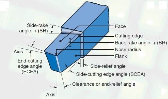
Let’s study one by one in detail.
Shank:
It is the main body of the tool. Shank is always held in the holder. It is the back portion of the tool which is held by the tool post.
Flank:
Flank is the surface that are vertical and adjacent to the cutting edge. There are two types of flank i.e. Side flank (major flank) and end flank (minor flank).
Face:
The face is the top surface of the tool so that after cutting chips slides over it. The faces are the horizontal surface just adjacent to the cutting edge.
Heel:
The heel is the intersection of the base and the flank of the tool.
Nose:
The nose is also called the cutting point of the single-point cutting tool. It is the intersection point of major cutting edge and minor cutting edge.
Nose Radius:
The nose is given radius or gives the circular arc(nose) and it is the intersecting area of the major and minor cutting edge.
By giving a curve to the nose it will impart strength to the single-point cutting tool. Nose radius plays an important role in the surface finish of the final product.
Cutting Edges:
The cutting edges are prepared by grinding. It is the edge on the face of the tool which removes the material from the workpiece.
Now we are moving to different types of angle definitions,
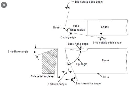

Side Cutting Edge angle:
Side cutting edge angle is the angle between the side cutting edge and the line extending the shank. The angle is measured in a plane parallel to the base.
Feed shows the uncut chip thickness and the depth of the cut shows the width of the chip. The width of the chip is the length of the cutting edge covered by the chips and it can be observed in the analysis that as side cutting edge angle increases chips become wider.
Uncut chip thickness is feed experienced by the side cutting edge in the perpendicular direction and by increasing the side cutting edge angle, chips become thinner.
Wider chips increase the friction force so increasing the side cutting edge angle cutting force requirement is slightly increased.
But, since the heat is distributed over the larger area, peak temperature over the rake face will decrease.
This will decrease, the tool wear, and hence the tool life, Side cutting edge angles increases the possibility of chatter vibrations. For machining shoulders, a small negative side cutting edge angle of 2 -5° is given on tools.
Normally the value of Sidecut Side cutting edge angle varies between 15-30°
End Cutting Edge Angle:
End Cutting Edge Angle Is the angle between the end cutting edge and the line passing through the tip perpendicular to the tool axis and the angle is measured in a plane parallel to the base.
At smaller values of the angle, larger forces normal to the machine surfaces are produced and the tool may chatter. Side cutting edge angle is made zero for a distance slightly greater than the feed in order to decrease Tool marks due to feed marks.
The normal value of this angle is in the range of 8-15 degrees.
Back rake angle:
Back rake angle is the angle between the line parallel to the tool axis passing through the tip and the rake face and angle are measured in a plane perpendicular to the base.
After plastic deformation chips flow over the rake face and heavy drag exists between chip and rake face.
Due to this, the temperature continues to develop and the maximum temperature will appear 2-3 mm away from the cutting edge. At high temperatures, carbon starts diffusing from the tool to the chip and as a result of that tool becomes weaker and weaker.
Due to the drag between the chip and the tool, a portion of the tool will be carried away by the chip. This phenomenon is called diffusion wear.
While machining ductile or brittle materials, smaller rake angles are used. For example machining brass, zero-degree rake angles are chosen.
If the tool material is brittle like ceramics and carbides negative back rake angles have to be provided because we want to make the tool stronger.
By providing the negative back rake angle energy required to overcome the friction increases which increases the overall power requirement in machining but negative rake angles are required for tool stability.
Because due to the impact created by fayalite, the tool may break.When machining slots or keyways the cutting tool may be given a negative back rake and positive side rake.
For machining ductile materials tool life increases by increasing the back rake angle because of a decrease in contact length between chip and tool over the rake face. But when this angle becomes more than a particular value, the lip angle of the tool decreases. This decreases the strength of the tool hence tool life decreases.
The optimum back rake angle of ductile materials is around 10-15 degrees.
Side Rake angle:
Side Rake Angle is the angle between the rake face and the Line passing through the tip perpendicular axis and the angle is measured in a plane perpendicular to the base. Normally this angle varies 5-15 degrees.
Side Relief Angle:
Side relief angle is the angle between the side flank and the line passing through the tip perpendicular to the base and the angle is measured in a plane perpendicular to the tool axis. This angle varies in the range of 5-15°.
The workpiece material which is going to be removed in the next revolution will try to hit the side flank due to the elastic recovery of the workpiece material. To avoid this rubbing side relief angle is provided.
End Relief Angle (Clearance angle):
End relief angle is the angle between the end fink and the line passing through the tip perpendicular to the base and the angle is measured in-plane parallel to the tool axis. There will be some elastic recovery in the finished work and as a result of that, it will try to rub the end flank.
Relief is provided to the side and end flanks in order to minimize physical interference or rubbing contact with the machine surface of the workpiece. Smaller relief angles do not weaken the cutting edge as much as the larger relief angles.
Single Point Cutting Tool Geometry Vidoe:
Single Point Cutting Tool Material:
This cutting tool can be made from various materials such as Cerements, Diamonds, Ucon, Cemented carbide, High carbon steel, High-speed steel, Ceramics, and CBN (Cubic boron nitrite).
Single Point Cutting Tool Advantages:
The main advantages of single point cutting tool are:
- Price is low comparatively multi-point cutting tool.
- Design and fabrication are easy.
Single Point Cutting Tool Disadvantages:
There are disadvantages too, the main disadvantages of single point cutting tool are:
- The tool wear rate is high.
- Low metal removal rate.
- Low productive and
- The tool life is shorter.
The above-listed disadvantages are written comparatively Multi-point cutting tools.
Internal Resources:
External Resources:
- https://en.wikipedia.org/wiki/Cutting_tool_(machining)
- https://www.sciencedirect.com/topics/materials-science/cutting-tool
Here we studied single point cutting tool in detail. Now I want to know from you that have you understood or not?
If you find this article helpful then please checkout our other articles too.


![What is Gear Cutting? Different types of Gear Cutting Processes? [Notes & PDF] feature image of Gear Cutting Process](https://themechanicalengineering.com/wp-content/uploads/2022/01/feature-image-of-Gear-Cutting-Process-300x189.jpg)
![What is Bolt? Different Types, Geometry, and Material [Notes & PDF] Feature Image of Bolt](https://themechanicalengineering.com/wp-content/uploads/2022/06/Feature-Image-of-Bolt-300x167.jpg)
![Propeller Shaft: Definition, Characteristics, Construction or Parts, Types, Material, Advantages, Application [Notes & PDF] Propeller shaft](https://themechanicalengineering.com/wp-content/uploads/2021/08/Feature-Image-of-Propeller-shaft-300x169.jpg)
![Flywheel: Definition, Function, Construction, Working Principle, Material, Advantages, Application [Notes & PDF] Feature Image of Flywheel](https://themechanicalengineering.com/wp-content/uploads/2021/09/Feature-Image-of-Flywheel-300x200.jpg)
![Crankshaft: Definition, Parts, Working, Types, Material, Advantages, Application [Notes & PDF] Feature Image of Crankshaft](https://themechanicalengineering.com/wp-content/uploads/2021/12/Feature-Image-of-Crankshaft-300x226.jpg)
Discussion about this post