In this article we will study the Definition, Construction or Parts, Working Principle, Advantages, Disadvantages and Application [Notes & PDF] of Pelton Wheel Turbine in detail.
So lets start with the definition,
Pelton Wheel Turbine Definition:
Pelton Wheel Turbine is the type of impulse or hydraulic turbine which is used for high heads for the generation of power. In this, the jet after leaving the nozzle runs in the open air and strikes the bucket or vane.
The Pelton wheel turbine is developed by Lester Allan Pelton, who is an American Engineer.
Now come to construction or Main parts of Pelton Turbine,
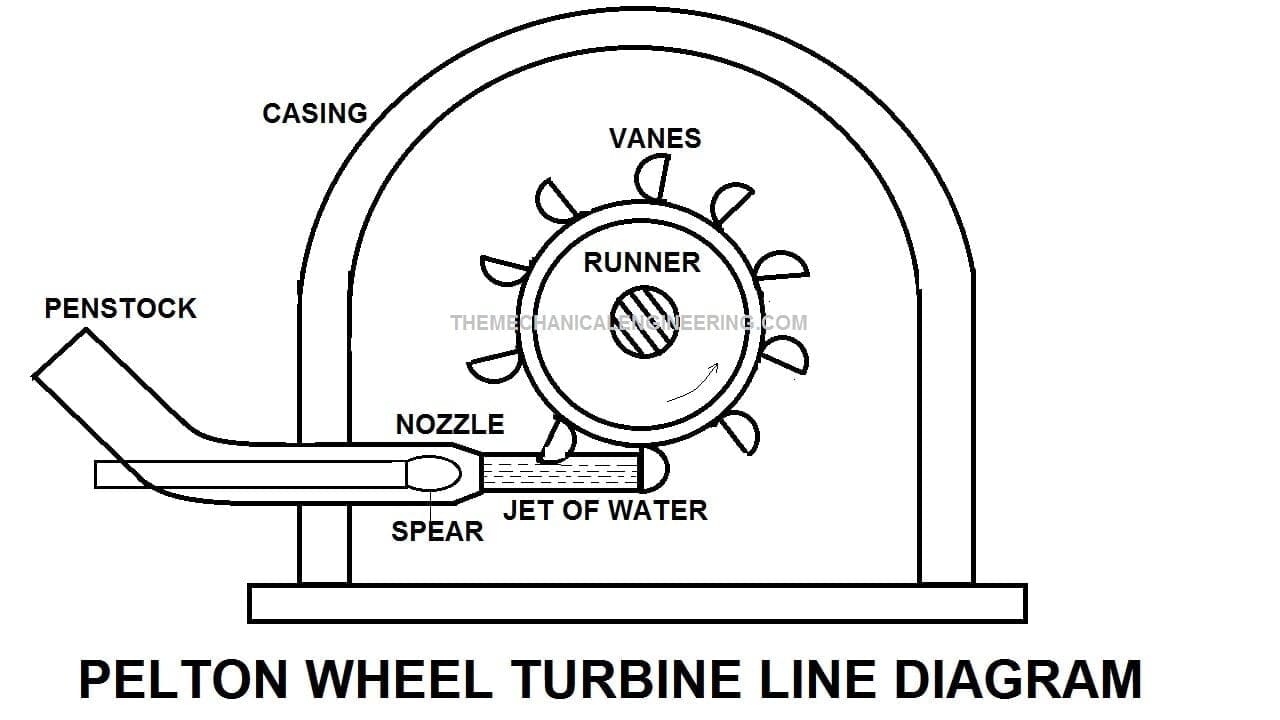
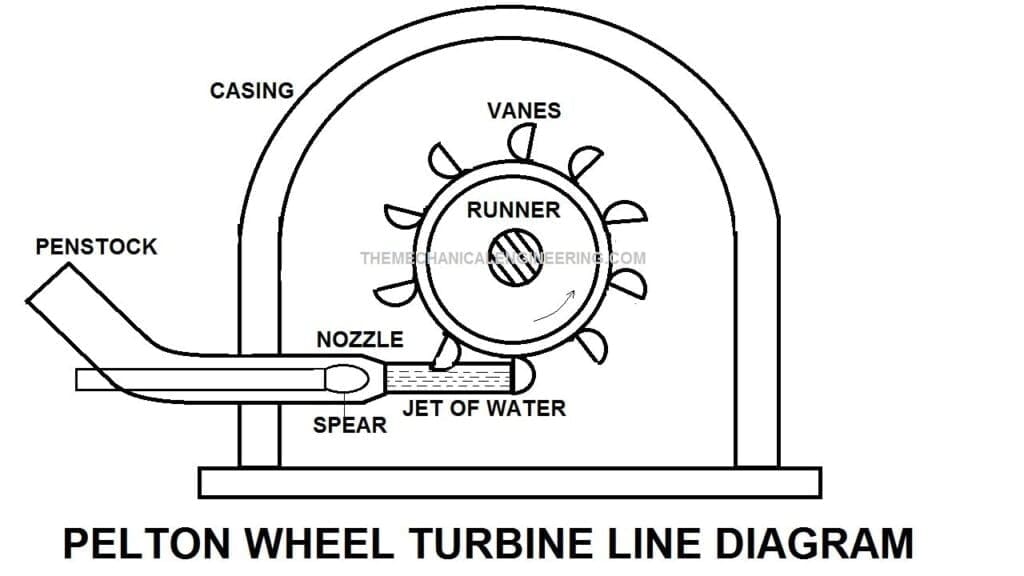
Pelton Wheel Turbine Construction or Parts:
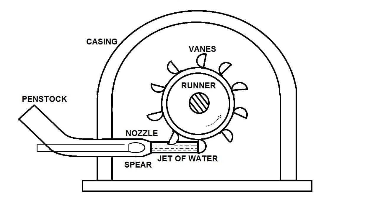
The following construction or parts of Pelton wheel Turbine:
- Casing
- Spear
- Break Nozzle
- Runner or Rotor
- Penstock
- Governing Mechanism

Now we will study one by one in detail,
Casing :
The Pelton wheel casing prevents the splashing of water and it will provide a discharge of water from the nozzle to the tailrace.
The casing surrounding the wheel has no hydraulic function to perform, unlike the reaction turbine where the casing plays an important hydraulic function.
Spear:
Needle Spear will control the water flow and it moves insides the nozzle and provides smooth flow so there can be very less energy loss.
When the nozzle is completely closed by moving the spear in the forward direction the amount of water striking the runner is reduced is zero but the runner due to inertia continues revolving for a long time.
Break Nozzle:
To stop the runner to rest in a short time a breaking jet is provided which directs the water on the bucket. this is called breaking jet.
Runner or Rotor:
A Pelton wheel has a runner that rotates and has kinetic energy, at the periphery of the runner equally spaced hemispherical or double ellipsoidal buckets.
All the potential energy is converted into kinetic energy before it strikes jet hits the rotor blades
Penstock:
These are the channels or pipelines from high head source water is transferred to the actual power station
Governing mechanism:
Governing of Pelton turbine is done by means of oil pressure governor, which consists of the following parts:
- Oil sump.
- The spear rod or needle.
- Pipes connecting the oil sump with the control valve and control valve with servomotor.
- The centrifugal governor or pendulum which is driven by a belt or gear from the turbine shaft.
- The control valve or the distribution valve or relay valve.
- The servomotor also called the relay cylinder.
When the load on the generator decreases, the speed of the generator increases this increases the speed of the turbine beyond the normal speed.
The centrifugal governor which is connected to the turbine’s main shaft will be rotating at an increased speed. Due to an increase in the speed of the centrifugal governor, the flyballs move outward due to the increased centrifugal force on them.
Due to the upward movement of the flyballs, the sleeve will also move upward. A horizontal level supported over a fulcrum connects the sleeve and the piston rod of the control valve.
As the sleeve moves up, the lever turns about the fulcrum, and the piston rod of the control valve moves downward. Close the valve V1 and open the valve V2.
The piston along with the piston rod and spear will move towards the right. This will decrease the area of the flow of water at the outlet of the nozzle. This decrease in the area of flow will reduce the rate of flow of water.
Now Working,
Pelton Wheel Turbine Working Principle:
The working principle is water is coming from the storage reservoir through a penstock to the Inlet of the nozzle which is the inlet of the turbine so the hydraulic energy of the water is mainly converted into kinetic energy.
The water releases in the form of a jet from the nozzle and strikes on the vanes for a very small time duration.
Since a very high force is exerted on the vanes by the jet of water for a very small time duration so these turbines are known as Impulse turbines.
Bucket changes the direction of run/flow of water jet and momentum transfer takes place.
All events happen in open air i.e at atmospheric pressure. The nozzle is used to convert the head available with water into a dynamic head and the water comes out from the nozzle in the form of a jet.
As the jet strikes over the runner vane, it will apply a large magnitude force for a small amount of time over the runner called Pelton force the Pelton force will rotate the runner.
Here you can watch Pelton Wheel Turbine Video Working:
Hydraulic Efficiency of Pelton Turbine:
Water may be allowed to enter a part or whole of the wheel circumference and the wheel/turbine does not run full and air has free access to the buckets.
Always installed above the tailrace. No draft tube is used either remaining constant or reduces slightly due to friction
V1= absolute velocity of the jet before striking the bucket
V2 = velocity of the jet leaving the bucket (absolute)
u1= absolute velocity of bucket considered along the direction tangential to the pitch circle
Vr1=velocity of the incoming jet relative to the bucket
β = angle between v2 with the direction of motion of vane at the outlet
ϕ = angle made by vr2 with the direction of motion of vane at the outlet, vane angle at the outlet
Vr2=velocity of the jet leaving the vane
©= Angle through which the jet is deflection by the bucket (180-¥), where ¥ is the angle of the bucket at the outlet tip
Since the velocities V and u are collinear, the velocity triangle at the inlet tip of the bucket is a straight line and thus
Vr1= (V1-u1) and (Vw1- u1) and alpha=0 and theta=0.
At the outlet tip, any one of the three velocity triangles is possible. Depending upon the magnitude of u1 corresponding to which it is a slow, medium, or fast runner.
As the inlet and the outlet tip of the bucket are at the same radial distance, the tangential velocity of the bucket at both the tips is the same i.e u1=u2
Further, the relative velocity Vr2 with which the jet leaves the bucket will be somewhat less than the initial relative velocity Vr1 at the inlet tip.
This is because, although the inner faces of the buckets are polished so as to minimize frictional losses as water flows over them, such losses cannot be completely eliminated.
Vr2=KVr1, where k is the blade coefficient.
In addition to this, some loss of energy will also take place as the jet strikes the splitter these losses of energy reduce the relative velocity between the jet and the bucket,
Thus the hydraulic efficiency is maximum when the bucket speed is equal to half the velocity of the jet satisfying this condition the maximum hydraulic efficiency is obtained as
1/2{(1+K cos (phi))}
Hydraulic Efficiency of Pelton Turbine Video:
Pelton Wheel Turbine Head Types:
- Gross Head
- Net Effective Head
Gross Head:
The gross head is the difference between the water level at the reservoir and the water level at the tailrace. It is denoted by Hg.
Net or Effective Head:
The head available at the inlet of the turbine is known as the net or effective head. It is denoted by H and is given by [H=Hg-Hf-h]
Now coming to different types of efficiency,
Different types of Efficiency in the Pelton Wheel Turbine:
There are four different types of efficiency and those are:
- Hydraulic Efficiency
- Mechanical Efficiency
- Overall Efficiency and
- Volumetric Efficiency.
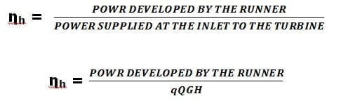
Hydraulic Efficiency:
It is defined as the ratio of power developed by the runner to the power supplied by the jet at the entrance to the turbine.
Mathematically,
hydraulic efficiency = (Power developed by the runner) / (Power supplied at the inlet of the turbine)
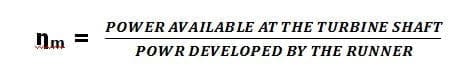
Mechanical Efficiency:
It is defined as the ratio of the power obtained from the shaft of the turbine to the power developed by the runner.
These two powers differ by the number of mechanical losses, viz, bearing friction, etc
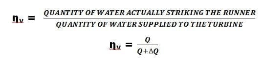
Volumetric Efficiency:
The volumetric efficiency is the ratio of the volume of water actually striking the runner to the volume of water supplied by the jet to the turbine.
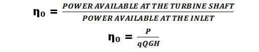
Overall Efficiency:
It is defined as the ratio of the power available at the turbine shaft to the power supplied by the water jet.
Overall efficiency = (Power available at the turbine shaft) / (Power available from the water jet)
Pelton Wheel Turbine Advantages:
The following adavnatages of Pelton Turbine are:
- The Pelton Turbine simple in design and also the construction is not complex.
- The water which is clean cannot cause very rapid wear in high heads.
- The overhaul and inspection are much easier than another turbine.
- Cavitation is not an ever-present danger.
- The water hammer effect is not there.
- The overall efficiency is quite high as compared to reaction turbines.
- There is no requirement for the draft tube here.
- It can work on relatively less Q(discharge) of flow rate.
- In the Hydraulic Turbine, it is the most efficient turbine.
- The parts assemble of the Pelton turbine is very easy. No complexity here.
- The water striking and leaving the runner at atmospheric pressure only.
- This is a tangential flow turbine. It can move in axial flow or radial flow direction.
Pelton Wheel Turbine Disadvantages:
The following disadvantages of Pelton Wheel Turbine is:
- In the Pelton turbine, the variation in the operating head cannot be easily controlled because it works at high heads.
- The ratio of maximum and minimum operating heads can be even less.
- The operating head cannot be utilized when the variation in the tailwater level is relatively large when compared to the total head.
- The mechanical efficiency of the Pelton wheel decreases faster compare to the Francis turbine.
- The size of the runner, generator, powerhouse required is large and not economical if the Pelton turbine is used instead of the Francis turbine for the same power generation.
Pelton Wheel Turbine Application:
The following application of Pelton Wheel Turbine is:
- The Pelton Turbine wheel turbine is used in Hydro Power Plant where Less discharge and High Heads are required.
- This is used to get more velocity of the fluid for maximum power and efficiency [Because the turbine and wheel are designed in such a way that the water jet velocity is twice the rotating bucket velocity].
- It is also used to drive the generator and who is attached to the turbine shaft here the Mechanical energy gets converted into Electrical Energy.
So here we finally studied the Pelton wheel turbine in detail. If you have any doubt feel free to ask in the comment box. Till then do not forget to share on social media.


Discussion about this post