In this article, we will study the Reaction Turbines in detail. Starting with What is Reaction Turbine? then construction later different types in detail.
Note: The PDF of this article you can download at the end of the articles.
Without further delay, let’s start our topic,
What is Reaction Turbine?
Reaction turbines are the type of turbine that formulates torque by countering the pressure or mass of a vapour or liquid. It utilizes the pressure as well as the momentum of the striding liquid to fluctuate.
The reaction turbines operate on the principle of Newton’s third law of motion and the reaction is exact and distinct.
It is called a reaction turbine because the turbine is propelled by the reaction force occurring from the momentum of vapours through the convergence of the edge path.
The reaction turbines are normally used for zones with elevated flows and deeper heads and they are the most popular species of turbine consumed in the United States.
Distant from cross-flow turbines the reaction turbine is the only turbine to accomplish excellent strength production at deep peak water head and elevated speed, which is not profitable.
Reaction turbines are operated in wind energy mills to produce electricity. It is the abundantly widely wielded turbine for generating electricity in hydroelectric factories.
Now we will see construction in detail.
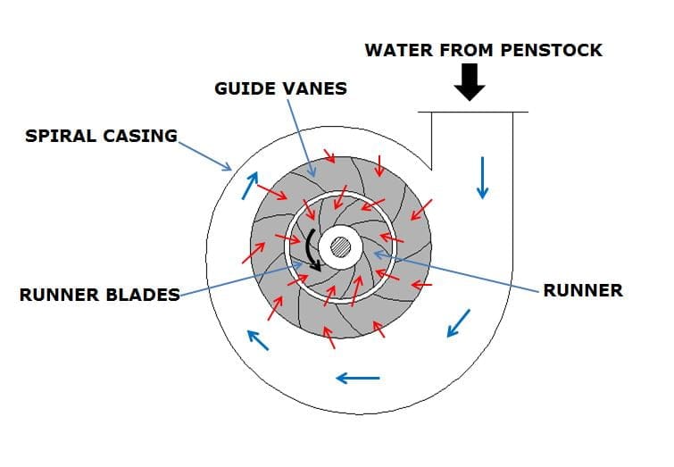
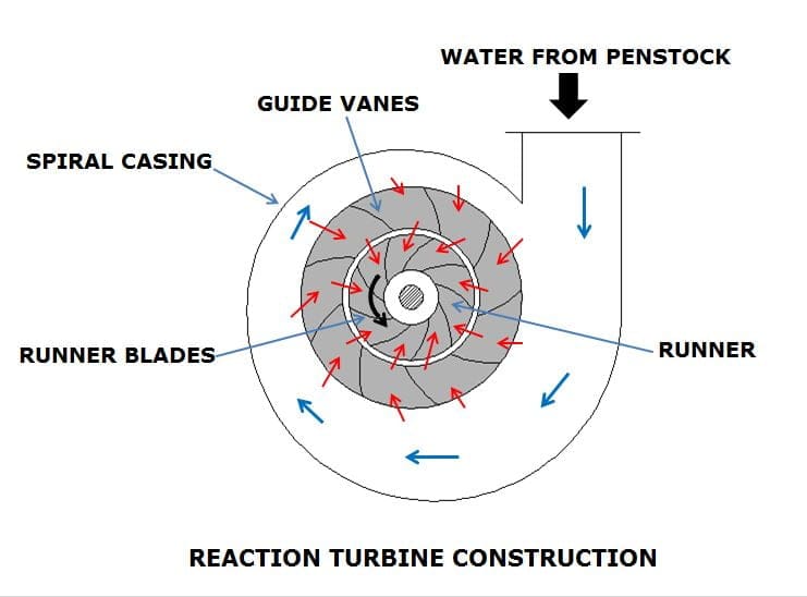
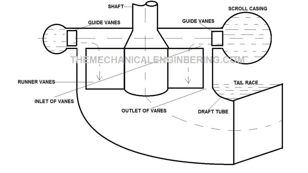
Reaction Turbine Parts or Construction:
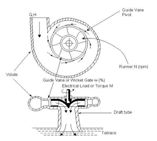
The following parts of the Reaction turbine are following:
- Guide vane
- Draft tube
- Spiral casing
- Runner and
- Volute
#1. Guide Vane:
Guide Vanes have stabilized holes set up in turbines that assist direct liquid, vapour, or air around corners at absolute efficiency.
When the impellers gain or drop the discharge of a material through a procedure, the guide vane in the turbine makes certain that the equipment is passed evenly and as smoothly as apparent.
These are mended between two hoops in the aspect of a rotation.
The function of guide vanes is to allow water to reach the runner without impact.
#2. Draft Tube:
The draft tube is one of the significant components of a reaction turbine and pertains to runner entry to tag class.
The major processes of the draft tube are to authorize the establishment of a turbine above the bottom race category without failure of the head and to transmit an important portion of kinetic power reaching out of the carrier into stress power or pressure energy.
#3. Spiral Casing:
The Spiral casing is a valuable element of the reaction turbine which is used for the rightful measurement of the kinetic and potential energy of the liquid to accomplish the mandatory conclusion for reasonable execution of the runner in the turbine.
This conserves a continual speed straight through various entrances that have been given for the fluid to attain the blades because the cross-sectional region of the casing lessens notify them along the perimeter.
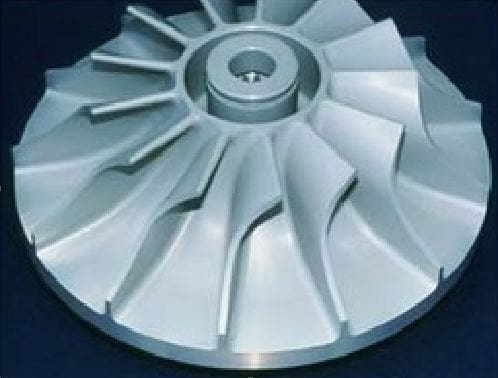
#4. Runner:
The runner is called the essence of the turbine. The runner is where liquid power is converted into the rotational force that propels the generator in the turbine.
Nevertheless of the carrier type, its pails or blades are credible for catching the most apparent energy from the liquid. Personal awareness of the layout or structure of the blade curves at the inlet and outlet is essential because these are important parameters involving energy generation.
#5. Volute:
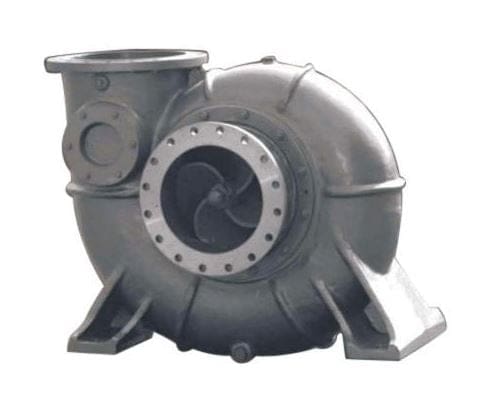
Volute is a spiral-shaped pump casing repeatedly utilized in centrifugal pumps.
The major purpose of a volute in a radial or mixed flow turbine is to strengthen the rotor with the ensemble progression at the desired intersection to optimize the execution.
The measurement of A/R rapidly impacts the progression angle diffusion at the rotor straight, having a substantial consequence on the turbine operation.
How does Reaction Turbine works?
The working principle of the reaction turbine is based on Newton third law of motion. The water enters into the spiral casing with high velocity and low heads.
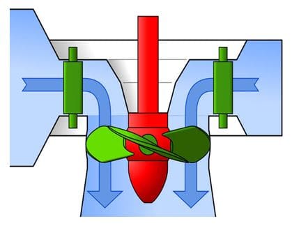
It starts flowing through guide vanes into runner blades. The main function of guide vanes is to guides the flow of water to strike the blades of the runner at an actual angle to generate maximum power output.
During water flowing in the spiral casing, its pressure energy is being consistent all over the circumference of the casing, because the cross-sectional area is decreasing uniformly.
Now there is a shaft that is attached with the casing, rotor, Gearbox and Generator.
A rotor contains a nozzle that releases water at high pressure.
When the water leaves the nozzle it experiences a return or reaction force that rotates the nozzle at a very high speed. And also a reaction force is generated by fluid moving on the runner blades. Because of the reaction force, the runner rotates.
The mechanical energy is converted into rotational energy and the rotor is attached to the gearbox and generator so here the rotational energy is converted into electrical energy and further it is connected to the transmission line.
And the water enters the draft tube and to the tailrace after moving over the runner blades.
The Water which is coming out after striking the runner blades has low pressure, so it is passed through a draft tube to recover its pressure as it reaches the tailrace. The draft tube has a uniformly increasing cross-sectional area.
But unfortunately, the pressure difference is too high to be recovered by a draft tube, so this results in the problem of cavitation and corrosion.
What is cavitation in Reaction Turbine?
When the water enters into the turbine we measure the pressure at that point and when it exits after striking the runner blades here also measure the pressure.
If there is a high-pressure difference, then due to this difference in pressure the air molecules which is having high-pressure enter into the casing in the form of bubbles.
This bubble keeps on exploding near the surface of the runner blades continuously causing a shock wave, and its defects at the runners surface. That is what we called cavitation.
And due to this cavitation process, the turbine efficiency is low and also in some cases it causes wear and tear if it is not fixed.
How to prevent cavitation from the Reaction turbine?
We can opt for a hard surface material like stainless steel to overcome cavitation or we can also go with surface Hardening of the runner blades, to prevent them from cavitation.
Different Types of Reaction Turbine:
Based on the direction of flow of liquid through the wheel the reaction turbine can be classified into the following kinds:
- Radial flow turbines
- Inward flow turbine
- Outward flow
- Axial flow turbines
- Kaplan Turbine
- Propeller turbine
- Mixed flow turbines
- Francis Turbine
- Gravity Turbine
- Bulb and
- Kinetic Turbine
Radial flow turbines:
The radial flow turbines are the turbines in which the flow of water is radial as in it is along with the radius of the rotation or wheel.
In a radial inpouring turbine, the progression reaches the nozzle blades in the radial orientation or the outbreak of a spin tangentially developing volute.
Described as an axial flow turbine, the radial flow turbine can operate at a somewhat elevated pressure rate (≈4) per phase with shorter progression ratios.
The flow arrives at the rotor blades in the radial orientation, is twisted in the rotor path and departures along the axis of the wheel. The radial flow turbines may be also subdivision into another two types:
- Inward flow turbine and
- Outward flow turbine
Inward flow Turbine:
In the inward flow turbines, the water reaches the wheel at the exterior boundary and then streams towards the centre of the wheel or inward.
In this turbine, the exterior diameter of the carrier or runner is equal to the inlet and the inner diameter is a duct. The runners in this turbine are enclosed by a guide mechanism.
The inward flow radial gas turbine has been utilized to leverage automotive turbochargers, development departments in vapour liquefaction, aeroplane secondary energy units, and cryogenic networks.
Outward flow turbine:
In the outward flow turbine, the water enters at the centre of the swirl and then streams outwards or towards the outer boundary of the wheel.
In this turbine, the internal diameter of the runner is the passage and the external diameter is a medium. The guide mechanism in this turbine is enclosed by a runner.
If the outward flow turbine velocity increases, the whirl manages to sprint as the turbine by itself can not adjust the speed.
Axial Flow Turbine:
The axial flow turbine is a turbine in which the flow of the working liquid is similar to the shaft; it is the exact opposite of the radial turbines, where the liquid operates around a cylinder like a watermill.
It can be said that the axial flow turbines convert the flowing liquid into rotating mechanical energy.
The axial flow in this turbine is developed by impellers with inclined or tipped blades that create an acute angle with the plane of rotation. Axial flow is extremely valuable when powerful upright currents are expected.
Types of reaction turbines in an axial flow turbine: Kaplan and Propeller Turbine.
Kaplan Turbine:
The Kaplan turbine is a propeller-type water turbine that contains flexible blades. It is named after the Austrian professor Viktor Kaplan who developed it in 1913, he combined the automatically modified propeller blades with automatically modified wicket gates to accomplish efficiency over a large range of flow and liquid levels.
This kind of turbine enables you to modify the blade curve or the impeller according to the needed energy. This permits the Kaplan turbine to labour according to the quantity alterations.
These turbines are widely used for electrical energy generation throughout the world. They surround the deepest head hydro sites and are particularly fitted for elevated flow circumstances.
Kaplan turbine builds tremendous growth to the small scale hydropower factories by producing high velocity of the shaft at very low head.
The Kaplan turbine is smaller in size. The efficiency of this turbine is very high as compared to the other types of hydraulic turbines. This turbine is very simple to construct and it needs a smaller area.
Kaplan Turbine Advantages and Disadvantages:
| Advantages | Disadvantages |
| The Kaplan turbine can work at a low head. | The Kaplan turbine has a problem with cavitation. |
| The number of blades in this turbine is less. | In this turbine, an elevated progression rate is required. |
| The Kaplan turbine requires less area. | These kinds of turbines are extremely costly to construct, manufacture and establish. |
| It retains flexible runner vanes. |
Propeller Turbine:
The propeller-type turbine is a type of turbine in which the flow is inward with a runner shaped propeller it can be seen in ships and submarines and it is provided with either remedied or elastic blades.
In the propeller turbine, the fluid progression is restrained by modifiable guide vanes which are also called wicket gates, the vanes stride the liquid into the runner to transmit the energy of the runner to the blades, the propeller turbine is usually assigned in hydraulic areas with elevated flow rates.
The major part of the runner is the propeller comprising the rotational intersection and blades to hold up the liquid capability and kinetic power to the cylinder connected to the turbine.
Propellers can be categorized by several procedures, such as the number of blades or blade tone.
The Fixed propeller-type turbines are commonly employed for huge units at deep heads, occurring in huge diameters and restricting rotational velocities.
As the name implies, the propeller-type turbine carrier or runner glances like the very enormous propeller of a boat or ship except that it fulfils the contrary goal.
Numerous types of propeller turbines accessible in the hydraulic energy initiatives are tube turbine, bulb turbine, strafe turbine and Kaplan turbine.
Propeller Turbine Advantages and Disadvantages:
Advantages:
- Impeller turbines are normally wielded for appeals in minor heads that are not adequate for other companions such as Francis turbines.
- Impeller turbines with flexible blades or guide veins can maintain optimal hydraulic efficiency to suit progression situations.
- Compactness is one of the benefits of factions of impeller turbines, exceptionally bulb turbines.
- They expect formation with lower costs and limited area.
Disadvantages:
- Plugging the generator and rotor in specimens such as drips and Straflo can make it hard to permit various elements for expenditure.
- Cavitation and its outcomes are some of the warnings that propeller turbines are perceived to be.
- The opportunity of fluid leaking into the generator lodging can result in damage to the hydroelectric operation.
- Propeller turbines usually expect an enormous quantity of liquid cycle to regulate.
Mixed Flow Turbine:
A mixed-flow turbine is an internal flow, a reaction-type liquid turbine in which the carrier or runner vanes are so shaped that they occur acted on by the liquid strength both axially and radially.
A mixed-flow turbine can be glimpsed as a hybrid method between an axial direction and a radial turbine as it captures the factors of both.
Correlated to a radial turbine, this diminishes the flow direction curvature and efficiently reduces minor progression construction.
The mixed flow turbine was such an attractive and desirable technique that it is restfully adopted and used today, like in turbochargers of the modern car; the turbochargers operate the mixed flow air input procedure to maximize the abundance of air reaching the motor cylinders.
The more will be the air the more eruptions will arise in the engine container which can generate more power outcomes.
Francis Turbine is one of the types of Mixed flow turbine.
Francis Turbine:
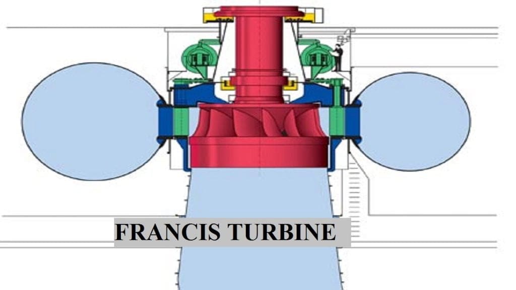
Francis turbine can be defined as a mixture of both impulse turbine and reaction turbine in the Francis turbine where the blades fasten utilizing both outcome and impulse force of liquid streaming through them so they can generate electricity better efficiently.
Francis turbine is used for the production of abundant electricity often in medium or large-scale hydropower locations. In the Francis turbine, the fluid enters these turbines radially implying that it enters the turbine perpendicular to the rotational axis.
Once entering the turbine, the water constantly streams inwards or towards the centre. Before the liquid retaining drift through the turbine, it departs axially and corresponds to the rotational axis.
The Francis turbines occurred in the initial hydraulic turbines that possessed a radial influx which was formulated by an American scientist James Francis.
Francis turbines are the vastly favoured hydraulic turbines. These turbines prevail as the most stable workhouse of hydroelectric power warehouses.
Francis turbine recharges approximately 60 per cent of the entire hydropower capability; this is mainly because it can operate efficiently under a large range of functioning conditions.
Francis Turbine Advantages and Disadvantages:
Advantages:
- The Francis turbine is precise to regulate rightfully with inconsistent lengths or sizes.
- The difference in its efficiency is extremely short over the duration.
- The passageway of the Francis turbine is slight in comparison to the other kinds of turbines.
- This turbine has a lower expenditure cost in comparison to the other kinds of turbines.
Disadvantages:
- Francis turbines are constructed for a particular progression.
- It is not a reasonable choice to utilize in a cloak of substantial flow differences since the achievement lowers.
- It illustrates difficulties when enabling with sizes enormous than 800 m.
- This turbine has a cavitation situation.
- The access of filthy water with components can result in considerable difficulties to the turbine.
There are some other types of turbines:
Gravity Turbines:
These gravity reaction turbines transform gravity force into rotational force. The gravity turbine converts the kinetic power of the gravity force into electricity.
Gravity Turbine is a perpetual motion energy concept; This technique maintains the potential to deliver free energy to the public, which could have a vital effect globally.
Bulb Turbines:
This turbine is a kind of propeller turbine. In these types of reaction turbine joining, the generator is surrounded and plugged in a streamlined watertight steel habitat discovered in the tube centre.
The generator pushes with the assistance of an unstable angle propeller at the downside end of the valve.
Kinetic Turbine:
Kinetic energy turbines are further called free-flow turbines which generate electricity from the kinetic energy existing in streaming liquid relatively than the potential energy from the head.
The procedures can operate in rivers and man-made channels, tidal waters, or ocean breezes. Kinetic strategies do not employ huge civil labours because they can utilize actual configurations, such as bridges, tunnels and tailraces.
Reaction Turbine Advantages:
The following advantages of Reaction Turbine are:
- The recation turbine equires less space as compare to Impulse turbine.
- It uses an oil-free exhaust system.
- The size of this types of turbine is not big and the turbine is easy to construct.
- It has a high capability to use high temperature and high pressure.
- The hydraulic efficiency of reaction turbine is high.
- It has a high working speed.
- The reaction turbine blades have high efficiency.
Reaction Turbine Disadvantages:
The following disadvantages are:
- The major disadvantages of reaction turbine is cavitation.
- Thrust force generates here.
- It require high maintenance as compare to an impulse turbine.
- The maintenance cost is also high.
- It des not have symmetrical blades.
Reaction Turbine Application:
The reaction turbine is used in the Hydro Power Plant and also the wind power plant for the generation of electricity.
Internal Resources:
- Impulse Turbine
- What is a Pump? What are the different types of Pump and their Working?
- Venturi Meter
- Orifice Meter
- Types of Fluid Flow
- Pump vs Compressor
- Francis Turbine
- Kaplan Turbine
- Rotary vs Reciprocating Compressor
- Difference Between Impulse Turbine and Reaction Turbine
- Difference Between Reciprocating Pump and Centrifugal Pump
Reference [External Links]:
- https://en.wikipedia.org/wiki/Turbine
- https://www.nitjsr.ac.in/course_assignment/FLUID%20MACHINERY-%20UNIT-02%20-reaction%20turbine.pdf
- https://nptel.ac.in/content/storage2/courses/112104117/ui/Course_home-lec28.htm
Conclusion:
Here we finally studied the Reaction turbines in detail. I hope you have understood this topic in detail. If yes then do not forget to share with your friends and family.
I have also explained the different topics of Fluid mechanics and machinery. If you want to read you can go through the URL attached above or you can search.




Discussion about this post