Hello, Hope you are well. In this article, we will discuss What are the different types of Gear Cutting Processes? in detail. First, we will see the Introduction, a little bit of history, and then we will study all the various types of Gear Cutting processes.
And at the end of the article, you can easily download a PDF version of this article.
Let’s start to introduction first,
Introduction to Gear cutting:
A gear is a vital constituent of machinery. It is a hard rigid element whose sole purpose is to transmit power or motion or both from one shaft of the machine to other.
It is a round blank wheel with a countable number of teeth along its periphery. The gears go through strenuous service conditions. It is important to design a gear as robust, reliable, highly efficient, and economical to meet the extensive demands in the fields of machinery.
The details in the design of gears make their manufacturing special. Making of gear is an exclusively precise job. Gear designs have remained standard along the centuries across the world.
The gear cutting is performed on special machines which are only designed to cut gears and nothing else. Over the years, there is a milling machine still not outdated that can perform multipurpose operations other than cutting of gears, but not suitable for large scale production of gears.
History of Gear cutting:
In ancient times, kind of round blank wheels was used to transmit motion and power. The friction wheels had a simple design as shown in fig. 1.0.
The wheels were simple round discs fixed at the ends of each shaft. The transmission of power was achieved by rolling the face of one shaft over the face of the other.
The mating parts rotated one another by the friction produced between them. Later, as an invention in 1897, Herman Pfuater invented the machine that can cut gears which lead a foundation to toothed wheels called to be as gears.
The gear cutting technique is being practiced from then to now.

Methods to manufacture Gears:
In the generation of automation, gears are being manufactured by three major methods.
- Casting
- Forming
- Metal removal
1. Casting:
Gears can be produced by various casting processes; the most common and economical process is sand casting. Gears of large size and modules can be manufactured at a low cost.
These gears are generally rough and inaccurate and so are their applications where operating noise and accuracy of motion are tolerated. Sand casting is suitable for one-off or small batches. Gears made by investment casting have a higher degree of dimensional accuracy with a good surface finish.
These can be manufactured by using strong materials to withstand large loads compared to gears made by sand casting.
Injection molding also produces gears of thermoplastics which can be used for low loads with greater accuracy and motion.
Shell molding is also used sometimes to produce small gears because it is the least expensive. However, casting does not meet the requirements of mass production of gears.
2nd method is forming process,
2. Forming:
Making of gears by forming method brings the roll forming, extrusion, and cold drawing process into action.
2.1 Roll forming:
In this process, a gear blank is mounted on a shaft and is forced to roll against rolling dies. Several numbers of revolutions are given. This pressing of die onto the blank wheel makes the solid to the toothed wheel.
Gears made by this process have greater strength and excellent accuracy. Roll forming is performed in both hot and cold depending on the application.
The gears produced by this method need no finishing operation. This method also saves a lot of material but the machinery used for this method of manufacturing gears is highly expensive.
The notable advantage of this method is that the gear becomes stronger in both tension and compression due to the plastic strain produced in the wheel and the teeth during the rolling process.
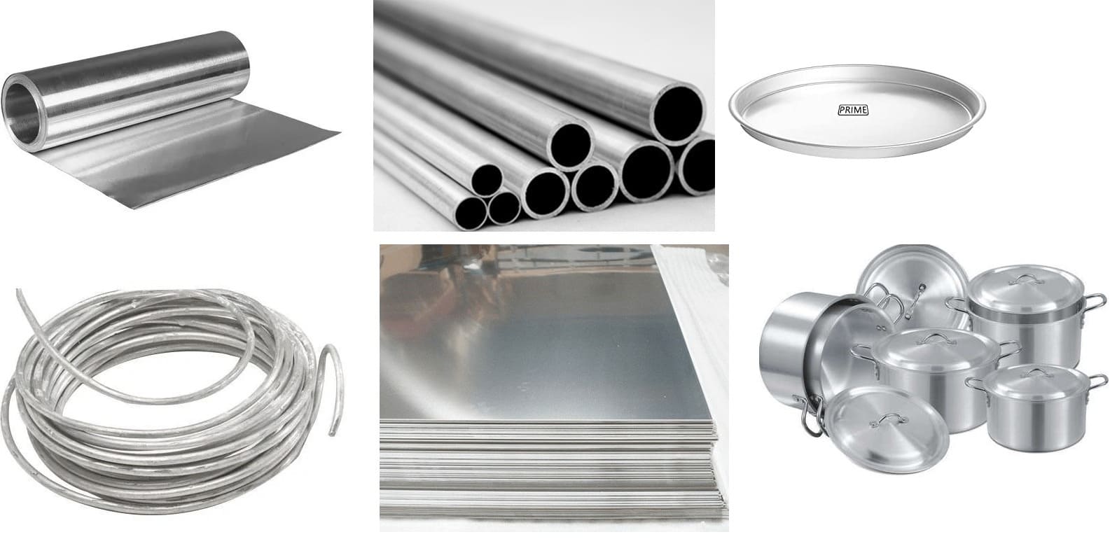
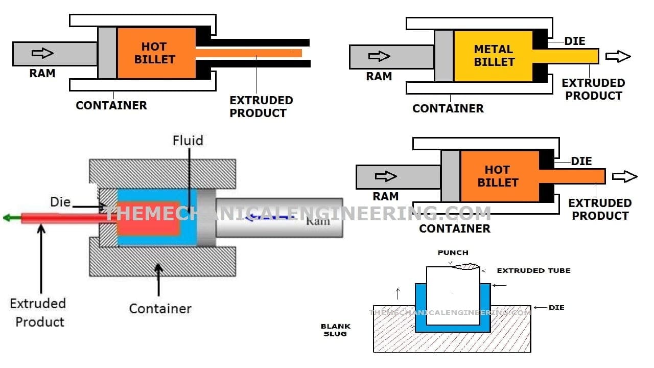
2.2 Extrusion & cold drawing:
Extrusion is the best method to make tiny gears of accurate dimensions.
In this method of manufacturing, a rod is cold drawn through a forming die to create gears on the entire surface of the rod along its length as shown in fig. 1.1. Then smaller lengths are cut off from the carved length of the bar.
Each small length is equal to the thickness of the required gear. Only finishing grinding is required to complete the job. Previously, aluminum, brass, bronze, and magnesium alloys were extruded.
But now steel bars up to 60mm dia. are being extruded in the manufacturing commerce. Gears produced by this method are most commonly used in watches, clocks, printers, typewriters, etc.

3. Metal removal:
As the name itself tells us, in this method blank wheels are machined to remove metal from the workpiece to produce gear tooth along its periphery.
Under this method of cutting gears, the main methods are:
- Profiling or Form Cutter Method.
- Generation Method.
3.1 Gear cutting by Profiling or Form Cutter Method:
In this method, a cutter is used to remove metal from the blank wheel. In many cases, the cutter has the same thickness, of space between each tooth of the gear. To operate, a single point cutting tool is used for the planer and shaper machine.
Whereas, in a milling machine, a round multitooth tool is used to profile gears on the workpiece. This method requires a special cutter for every different gear profile to be manufactured and is not suitable for large volume productions.
Various methods to cut gears under this method are as listed:
- Gear cutting on a milling machine with formed disc cutter or end milling cutter.
- Gear cutting on shaper or planer machine with a single point form tool.
- Gear cutting on a broaching machine.
- Gear cutting with form tool blades by shear speed process.
3.1.1 Gear cutting on a Milling Machine with a formed disc cutter:
Spur gear can be easily manufactured on a universal milling machine. In this principle of gear cutting, the solid blank wheel is mounted on the mandrel connected to the dividing head. The cutter is mounted on the arbor.
The axis of the cutter is always perpendicular to the axis of the gear blank as shown in fig 1.2. Next, the vertical axis of the blank wheel is properly matched with the horizontal axis of the cutter.
The table is then moved upward using a vertical movement crank until the nose of the cutter just touches the periphery of the gear blank wheel. The indexing movements are pre-calculated and are determined accordingly.
Then the knee is raised with the required height i.e., equal to the depth of teeth, and the vertical zero is set. Simultaneously the power is given to the cutter.
In a single pass, one tooth is finished, and the table is brought back to its starting position. This vertical movement may be less if the gear is to be cut in two or more passes. The gear blank is then indexed for the next tooth.
The same cycle of operations is repeated till the required number of teeth are cut along the periphery of the gear blank wheel.

For the making of helical gears or worms on a universal milling machine, a spiral milling attachment is used.
The helix angle is obtained by the use of the attachment in order to set the cutter and the gear blank wheel at an inclination to one another. In cutting of helical gears, a set of two cutters are used.
One for roughing and the other for finishing. These gears are also cut by the same sequence of operations discussed above.
To manufacture pinion of large pitch, the end mill cutters are employed at the place of disc type cutter. The end mill cutter is mounted on the milling machine spindle through a chuck.

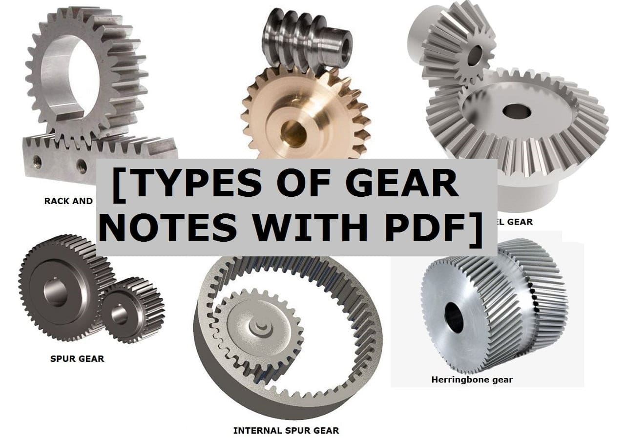
Producing gears on a milling machine is one of the simplest and most economical methods. The gears of type spur, bevel and helical, and also racks can be made by the gear milling method.
The quality of gear produced cannot be considered accurate since the motion of indexing is not precise.
3.1.2 Gear cutting on Shaper or Planer Machine with a Single point form tool.
Gears can also be manufactured on shaper, planer, or slotting machines. In this method of manufacturing, a single point form tool is used to scribe teeth on the blank wheel as shown in fig 1.3.
In all of these machines, the gear blank is mounted on a mandrel located between the tailstock and the dividing head. The dividing head of the milling machine can be directly bolted onto the table of these machines. In small productions, the gear blank is directly mounted in the chuck as shown in fig. 1.4.
The tool is securely mounted on the tool head. In each of these machines, the gear cutting is achieved by either reciprocating the tool against the workpiece or by reciprocating the gear blank wheel past the single point cutting tool.

In the case of both shaper and slotter machines, the gear blank wheel remains stationary in the chuck and in the fixture respectively, while the single point cutting tool reciprocates past the workpiece. The tool is affixed to the ram of the machine in both cases as shown in fig. 1.4.

In the case of the planer machine, the single-point cutting tool remains static while the table holding the blank wheel reciprocates past the tool. The depth of the teeth is adjusted by the movement of the tool head along the vertical axis. After cutting each tooth, the wheel is rotated along one direction by indexing.
Thus, the new tooth is cut by repeating the operations of reciprocating the tool or the blank wheel. This sequence is repeated until the required number of teeth are manufactured along the periphery of the blank wheel.
This method of gear cutting is cost-efficient and economical, but the major drawback is, the method is not suitable for large-scale production due to its slow cutting actions. Hence, this method is not widely used for gear making.
Comparison of gear cutting on shaper vs planer vs slotter machines:
| Shaper machine | Planer machine | Slotter machine |
| Gear blank wheel remains stationary | Tool remains stationary | Gear blank wheel remains stationary |
| Tool reciprocates past the blank wheel | The blank wheel reciprocates past the tool | Tool reciprocates past the blank wheel |
| The blank wheel is mounted in the chuck | The blank wheel is clamped on the work table | The blank wheel is clamped in a fixture |
| Less depth of cut | Higher depth of cut | Less depth of cut |
3.1.3 Gear cutting on Broaching Machine with a formed cutter:
Broaching is a machining operation performed on broaching machines. The tool that is used for broaching operation is called ‘broach’. This is a very quick process, here, the broach of a thickness of the gear is pushed or pulled past the inner or outer surface of the workpiece as shown in fig. 1.5.
This process has the ability to produce gears in a single pass whether it is internal or external. This method is economical and quick with a great surface finish.
The only limitation of this method is that it cannot be adopted for small-scale productions due to its expensive tooling.

3.1.4 Gear cutting with form tool blades by Shear speed process:
As the method title itself says, this is a speedy process. The cutting of all the teeth at a single pass or two to three passes makes this method exclusively fast.
This method is similar to broaching technique, but here, instead of one single point cutting tool, a number of cutting tools are arranged radially according to the required number of teeth to be cut on the periphery of the blank.
The process produces gears on both internal and external surfaces. For cutting external gears, the radial tool is mounted around a hollow head. For every stroke, the tool is fed with an incremental depth of cut.
A clearance is provided along every retard stroke of the tool. This method can be adopted to cut internal and external spur gears, splines, clutch teeth, and special gears in a large quantity.
Comparison of gear cutting by broaching process and shear speed process:
| Broaching method | Shear speed method |
| Only one single point tool is used | Multiple tools of the same dimensions are used |
| Broach tool is used | Radial form tool is used |
| One tooth is cut for one pass | All the teeth are cut for one pass |
| Quick process | Quicker process |
| Comparatively low cost | Comparatively high-cost tooling |
3.2 Gear generation:
In this automated era, the largest number of gears are being manufactured by the ‘Gear generation process’. The basic and important gear generation processes are:
- Gear cutting by shaper process.
- Gear cutting by rack planning process.
- The gear hobbing process.
3.2.1. Gear cutting by Shaper process:
The gear shaper operation can be performed in two different methods. One is the ‘rotary gear shaper cutter’ method and the other is the ‘rack type shaper cutter’ method. The basic principle of gear cutting is the same for both processes.

In this process, the gear blank is bolted onto the spindle shaft while the cutter is mounted on a stub arbor. The arbor of this machine has two axes of motion. One vertical or reciprocating motion and the second is rotary.
Here, a pinion-shaped cutter is used to scribe the metal from the blank wheel. The cutter is designed with a clearance on the tooth face and sides.
To cut the tooth, the cutter is reciprocated along the vertical axis in contact with the blank wheel thus the metal from the blank wheel is removed. The downward linear motion of the cutter in which the metal is cut is called cutting motion and the upward linear motion of the cutter to withdraw the latter is called the return stroke.
No metal is removed in return strokes. Along with every cut, a relative speed of rotation is given to the cutter and the blank wheel. The slow relative rotation between them is called indexing feed.
The gears trains connected between the shaft of the arbor and the spindle shaft rotate the cutter and the blank wheel slowly in directions opposite to one another to achieve the indexing motion as illustrated in fig 1.6.
The indexing and the reciprocating action of the cutter are continued till the required number of teeth are cut on the blank wheel.
In the case of rotary gear shaper cutter, the cutter used to decorate gears along the periphery of the blank wheel is a rotary pinion as illustrated in fig.1.7.
The tooth on the cutter is of the same number to be cut on the blank wheel. This method is widely used to generate gears because of its higher output and the ability to cut all types of gears except worms and worm wheels.
The rotary gear shaper cutting can also be adapted for cutting internal gears with the same principle of working. The rotary gear shaper machines are widely available in both vertical and horizontal spindle types.
Usually, the horizontal rotary gear shaper cutter machines have two powerful arbors. Each reciprocates in and out towards one another.

In the rack type gear shaper cutter method, a rack type cutter is used to remove metal from the blank wheel and make teeth. The principle of working is the same as the basic principle of gear shaper cutter.
It involves the rotation of the gear blank wheel while the rack-type cutter reciprocates along the vertical axis as exemplified in fig. 1.8.
The greatest limitation of this rack-type gear generation method is that the machining has to be paused every time the full length of the rack i.e., All the teeth of the cutter are utilized to reset the position to the first tooth of the cutter. While the greatest advantage is that, any gear of any number of teeth can be made.

3.2.2 Gear cutting by Rack planing process:
This process is mainly used to make gears of involute teeth. Spur and helical gears are the gear types that can be manufactured by this method.
The gears by this process can be made on two different machines; Sunderland and the Maag. Both the machines work on the same principle of cutting while the construction differs.
In the rack planning process, the blank wheel is bolted on the spindle of the horizontal axis, while the rack-type cutter is bolted on the arbor. To cut involute teeth on the blank wheel, the blank wheel is kept static while the cutter is reciprocating in forwarding and backward directions.
The cutter scribes two full teeth and two partial teeth as shown in fig1.9. and 1.10.
A little quantity of metal is removed in every forward and backward stroke. This type of improper scribing of teeth generates involute profile teeth. The gear blank is then gradually fed towards the rack type cutter, this motion makes the teeth of the cutter penetrate the periphery of the blank wheel.
As they penetrate into the blank, a slow rotary feed or the indexing feed is given to the blank wheel, this results in the generation of teeth. The principle of generation of involute profile teeth is as shown in fig. 1.9.
The same sequence of operations is repeated until the required number of teeth are made on the periphery of the blank wheel.

3.2.3 Gear cutting in the Sunderland process:
This process is named after its inventor ‘Sunderland’. The process works on the same principle discussed above, the rack planning process. In addition, here, in this process, the cutter also moves along with the gear blank and then suddenly withdraws, and steps back by an equal amount to one pitch distance.
This movement happens after the required depth of the tooth is achieved. An arrangement of a gear train is made to synchronize the movement of the cutter and the rotation of the blank.
Once the cutter is back into its position, the same reciprocating action is repeated followed by the indexing of blank and the movement of the tool with sudden withdrawal.
The schematic principle of working of Sunderland process is exemplified in fig 1.10. and 1.11.
In this method of gear generation, the operator is free to adjust the reciprocating speed of the cutter depending on the material.


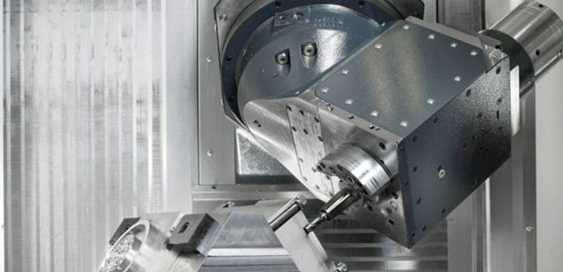
3.2.4 Gear cutting in the Maag process:
In this process, the blank wheel is mounted on the work table with its axis being vertical while the rack type cutter is mounted on a slide. The slide is free to make reciprocations along its axis.
The Maag process also works on the principle of rack plane. In addition, the cutter can be set to any inclination in the vertical plane, thus the cutter can cut gears in any desired direction. An industrial picture is shown in fig 1.12.

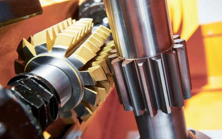
3.3.1 Gear Hobbing process or Gear cutting on a Hobbing machine:
In this process, the gear blank wheel is rotated against a rolling cutter called a hob. A hob is a tool that looks like a worm but carries several straight flutes cut all around.
The hob is mounted on the arbor while the blank wheel is mounted on the spindle. The spindle has the freedom to move in the vertical direction as well as to rotate around its central axis as exemplified in fig 1.13.

This process is mostly used to produce involute gears of all types. In this operation, the hob is given a suitable speed to rotate. Simultaneously, the blank is also made to revolve around its axis by a gear train arrangement.
The cutting teeth of the hob scribes the metal from the blank. Teeth of uniform depth are cut for every full rotation of the blank. Once the blank finishes its rotation, the depth of teeth is increased and the hobbing is repeated.
This sequence of operations is repeated until the desired depth of cut is achieved. The blank is also moved up and down to produce cuts of uniform depth along with the thickness of the wheel.
An industrial picture of gear hobbing is shown in fig. 1.14.
This process can produce gears on several blank wheels at the same time by mounting all the wheels one on another.
The hobbing is continuously operated on the set of blank wheels until the gears are produced on all the wheels. To cut helical gears, the spindle shaft of the blank wheel is tilted to a suitable angle.
Gear hobbing method is widely used around the world because of its ability to produce a vast number of gears of any type in less time. The only limitation of gear hobbing is that it cannot produce internal gears.

Why is the gear hobbing process widely used?
- This method is economical as compared to other generating processes.
- This is a faster and continuous process.
- All types of gears can be produced.
- Accurate dimensions are achieved.
- Several blanks can be machined at the same time by mounting them all one on another.
- Any number of teeth can be cut using the same hob.
The gears produced by all the casting, forming, cutting, and generation processes are sent for shaving, burnishing, grinding, and finishing before they are fit in any machinery.
Internal Resources for You:
Reference [External Links]:
- https://www.sciencedirect.com/topics/engineering/gear-cutting
- https://en.wikipedia.org/wiki/Gear_cutting
Conclusion:
Here we finally studied all the different types of Gear cutting processes in detail. I hope you have understood this topic in detail. If yes then do not forget to share with your friends and family.
I have also explained the different topics of Manufacturing Technology. If you want to read you can go through the URL attached above or you can search.

Discussion about this post