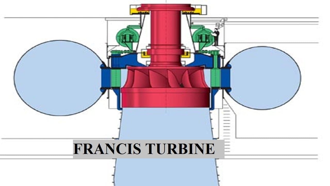
Francis turbine is a hydraulic and reaction turbine and it is the most preferable hydraulic turbine. Francis Turbine contributes more than 60 percent of hydraulic energy capacity to the world. The Francis turbine was developed by James B. Francis around 1855.
In this article, we are going to discuss the Definition, Construction or Parts, Working principles, Efficiency, Advantages, Disadvantages, and Application.
At the end you can download whole document in PDF format.
Now Let’s start with the definition first,
Francis Turbine Definition:
Francis Turbine is an inward flow reaction turbine and has a purely radial flow runner, the pressurized water will enter the vanes in the radial direction and discharge out of the runner axially. The Francis turbine operates under medium heads (45-400 meters) and also which are guiding types and it is employed to have medium discharge (10-700 cube meters per second).
Let’s move to construction,
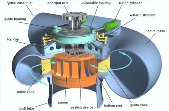
Francis Turbine Main Parts or Construction:
The following main parts or Construction of Francis turbine are:
- Penstock
- Casing
- Guide Vanes
- Governing Mechanism
- Runner and Runner Blades
- Draft tube
Let’s study one by one,
Penstock:
The penstock is also known as the Input pipe. The diameter lies between 1 to 10 meters. The penstock is a large size conduit that conveys water from the upstream of the dam or reservoir to the turbine runner.
Casing:
The casing has a passage that is the closed type and has a cross-sectional area gradually decreasing along the direction of the flow area and it becomes maximum at the inlet and zeroes at the exit.
Guide Vanes:
These vanes direct the water onto the runner at an angle appropriate to the design. The motion to them is given by means of a handwheel or automatically by a governor.
Governing Mechanism:
It changes the position of the guide blades/vanes to affect a variation in water flow rate when the load conditions on the turbine changes.
Runner and Runner blades:
The driving force on the runner is both due to impulsive and reaction effects. The number of runner blades will be around 16 to 24.
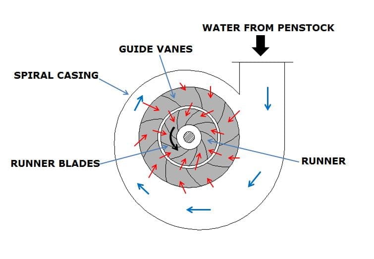
The modern Francis turbine is an inward mixed Flow reaction turbine. Water comes to the turbine via penstock and it will hit on no. of stationary blades. These stationary orifices are commonly called as guide vanes or wicket gates.
The head acting on the turbine is partly transformed into kinetic energy and the rest remains as pressure head. Due to this pressure difference, it is called a reaction turbine and is responsible for the motion of the runner that is why a Francis turbine is also known as a reaction turbine.
The Francis turbine the pressure at the inlet is more than at the outlet. After doing the work the water is discharged to the tailrace through a closed of gradually enlarging section like a tube. This is known as the draft tube.
Draft Tube:
It is an expanding tube used to discharge water through the runner and to the tail race. The main function of the tube is to reduce the velocity of (water flowing) at the time of discharge.
There are 3 types of draft tube:
- Conical Draft tube
- Elbow Draft Tube
- Moody Spreading Draft Tube
Francis Turbine Working Video:
Efficiency of Francis Turbine:
There are 3 main efficiency of Francis turbine:
- Mechanical
- Hydraulic and
- Overall Efficiency
Lets study the definition and formula,
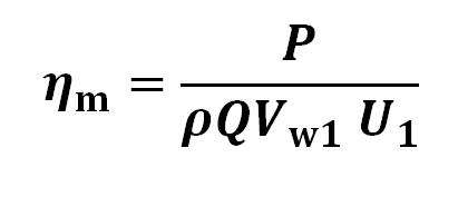
Mechanical Efficiency:
This can be defined as the ratio of actual work available at the turbine to the energy imparted to the wheel.
To find Mechanical efficiency the formula is,
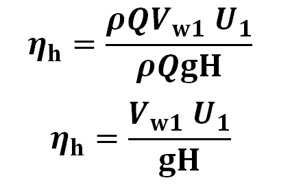
Hydraulic Efficiency:
Hydraulic efficiency can be defined as the ratio of work done on the wheel to the head of water energy supplied to the turbine.
To find Hydraulic efficiency the formula is,
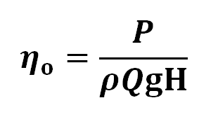
Overall Efficiency:
This can be defined as the ratio of power produced by the turbine to the energy supplied to the turbine.
Method to avoid Cavitation in Francis Turbine:
The following methods may be used to avoid cavitation:
- Runner/Turbine may be kept underwater. The other method to avoid the cavitation zone without keeping the runner underwater is to use the runner of a low specific speed.
- The cavitation free runner may be designed to fulfill the given conditions with extensive research
- The cavitation effect can be reduced by polishing the surface that is why the cast steel runner and blades are coated with stainless steel.
- It is possible to reduce the cavitation effect by selecting materials that resist better the cavitation effect. The cast steel is better than cast iron and stainless steel or alloy steel is still better than the cast.
- The cavitation may be avoided by selecting a runner of proper specific speed for the given head.
When the cavities collapse on the surface of a body due to repeated hammering action the metal particle give way ultimately due to fatigue indentation are formed this erosion of material is called pitting
The hydraulic machinery is affected by the cavitation in the following ways:
- The surface will become rough due to pitting
- The vibration produced due to cavities
- The amount of liquid flow will be reduced because the volume of cavities is much more than the volume of water from which they are formed which will be causing a sudden decrease in output and efficiency.
Francis Turbine Advantages or Merits:
The Francis turbine has following advantages:
- The variation in the operating head can be more easily controlled.
- In Francis’s turbine, the ratio of maximum and minimum operating heads can be even two.
- The operating head can be utilized even when the variation in the tailwater level is relatively large when compared to the total head
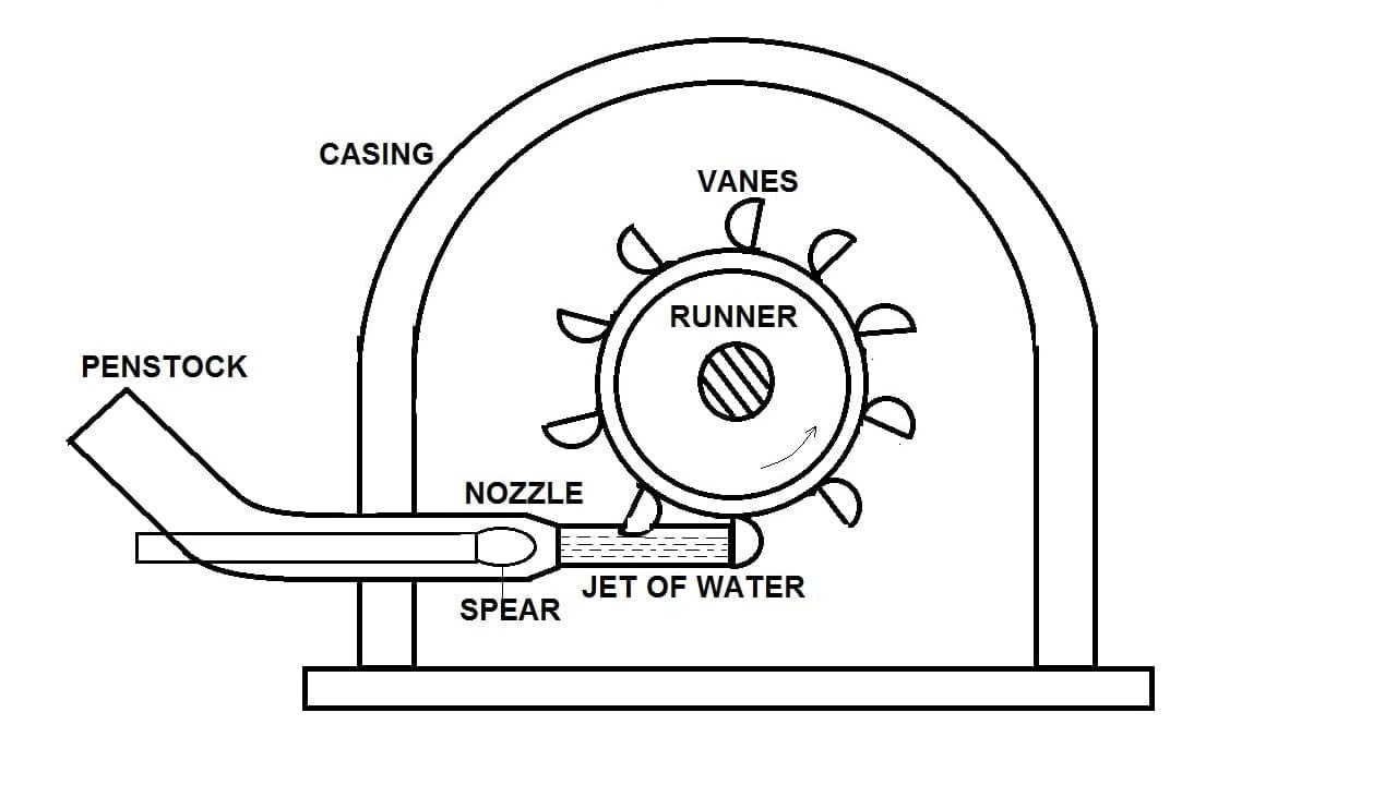
- The mechanical efficiency of the Pelton wheel decreases faster with wear than Francis turbine
- The size of the runner, generator, and powerhouse required is small and economical if the Francis turbine is used instead of a big Pelton wheel for the same power generation.
Francis Turbine Disadvantages or Drawbacks:
The following disadvantages of Francis turbine are:
- The Francis turbine will lose its efficiency if it is run a 50 percent load for max time.
- Water that is not clean can cause very rapid wear in high head Francis turbines.
- There can be difficulty in the overhauling of the turbine and also difficulties contained in the inspection.
- Cavitation is an ever-present danger.
- Chances of water hammer can be there.
Francis Turbine Application:
The following applications of Francis turbine are:
- This is the most efficient hydro turbine and used for the generation of Electricity.
- This turbine efficiency is great comparatively another turbine.
- It can be used for a wide range of water head and flow rates.
- In addition to electrical production, also be used for pumped storage, a reservoir is filled by the turbine (acting as a pump) driven by the generator.
Internal Resources:
So we have studied Definition, Construction or Parts, Working Principle, Efficiency, Advantages, Disadvantages, and Application. I hope this article gives you some information about the Francis turbine. If yes do share with your friends and social media too. We will again meet in another article.
Resources[External Lins]:


Discussion about this post