In this article, we will study the Definition, Parts or Construction, Working principles, Functions, Advantages, Disadvantages, and Application of Clutch in detail.
Notes: At the end of the article you can easily download whole document in PDF format.
Let’s start with the definition first,
What is Clutch Definition?
A clutch is a mechanical device that engages and disengages the power transmission means shaft, especially from the driving shaft to the driven shaft. When we have to change the gear in the transmission system then for that time we have to use the clutch.
When the clutch is engaged the power will flow from the engine to the wheels through the transmission system and the vehicle will move. When it is disengaged, the power is not transmitted to the wheels and the vehicles stop while the engine is still running. It is kept engaged when the vehicle is moving.
It also helps to take the gradual load so that there will be no impact. When it is properly operated it will prevent jerky motion or jerks on the vehicle. It is disengaged When we want to start the engine.
Clutches are useful in devices with two rotating shafts one will act as a driver and the other is a driven shaft. One of the shafts is typically driven by a motor or pulley and the other shaft is driving another device.
For example, In drill one shaft is driven by a motor, and the other drives a drill chuck. It connects the two shafts so that they can either be locked together and rotate at the same speed and also at different speeds according to our needs.
In a car, you need a clutch because the engine rotates all the time and the car wheels/tires don’t. If we want to stop the car without affecting the engine the wheel needs to be disconnected from the engine for that the clutch allows us to smoothly engage a rotating engine to a nonspinning of the engine by controlling the slipping between them. there should not be any slipping otherwise there will be power loss. Friction plays an important role in the principle of the clutch.
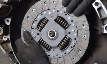
Clutch Construction or Main Parts:
- Flywheel
- Friction Disc
- Pressure Plate
- Spring
- Release levers
- Clutch release bearing and
- Linkage
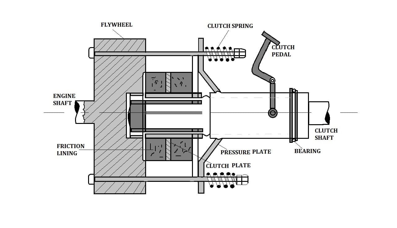
1. Flywheel:
The flywheel is used to store energy when there is excess energy and give it back to the system when we required it. It is mounted on the crankshaft keeps on running as long as the engine keeps running. The Flywheel contains a friction surface also known as a friction disc which is bolted to the outer side of the Flywheel.
2. Friction discs:
Single or multiple discs lined with friction material having a high coefficient of friction are mounted on the driven shaft. Friction provides the necessary ability to change the direction of the driving and driven shaft. They also consist of metal plates bonded.
3. Pressure Plate:
The purpose that it will act as a link between the engine and gearbox mainly it will transmit the torque obtained from the engine to the gearbox. Another friction disc is bolted to pressure plates. The pressure plate is mounted on the spline hub.
4. Spring and Release levers:
The spring used are diaphragm springs. The operation of spring is obtained with the help of levers. The release lever will light the force which is held on the spring when the clutch is disengaged.
5. Clutch Release bearing:
Transmits the movement of the clutch linkage to the pressure plate is usually a ball or roller type bearing and Self–centering to compensate for variations in alignment.
6. Clutch Linkage:
A clutch linkage mechanism uses levers and rods to transfer motion from the pedal to the fork when the pedal is pressed, the pushrod will push the bell crank and it reverses the forward movement of the pedal. The bell crank is connected to the release rod.
The release rod transfers the bell crank movement to the fork. It also provides how the adjustment of the clutch takes place.
Types of Clutch:
Here are the following different types of Clutch:
- Positive and Spline Clutch
- Friction clutch
- Single Plate Clutch
- Multi-plate Clutch
- Cone Clutch
- Centrifugal Clutch
- Hydraulic clutch
- Electromagnetic Clutch
- Hysteresis-powered Clutch
- Semi-Centrifugal Clutch
- Diaphragm Clutch
- Vacuum Clutch and
- Freewheel Clutch
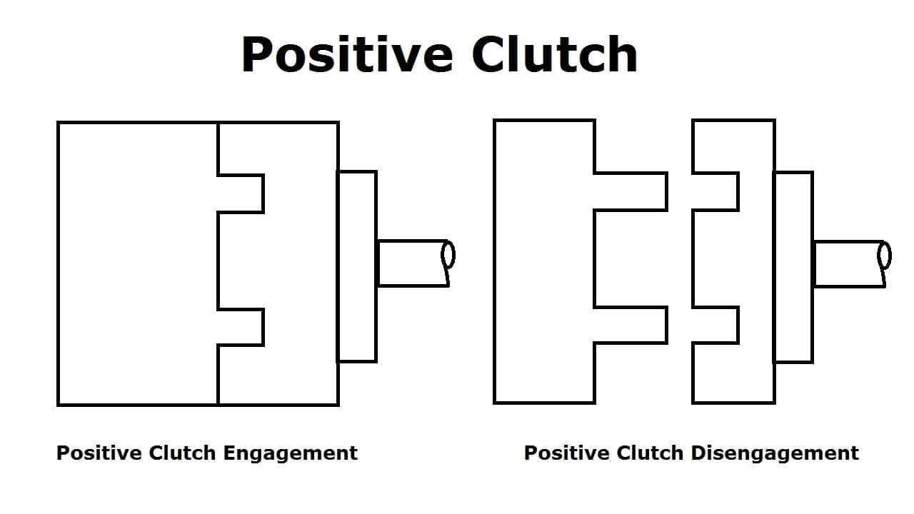
#1. Positive or Spline or Dog clutch:
In this, the grooves are cut either into the driving member or into the driven member, and specially designed parts are situated into both driving and the driven member.
The driver releases the clutch pedal then these special parts will insert into grooves and the driving and driven shaft start revolving together when he pushes the clutch pedal these parts come out from the grooves and the engine shaft revolve without the driven shaft.
#2. Friction Clutches:
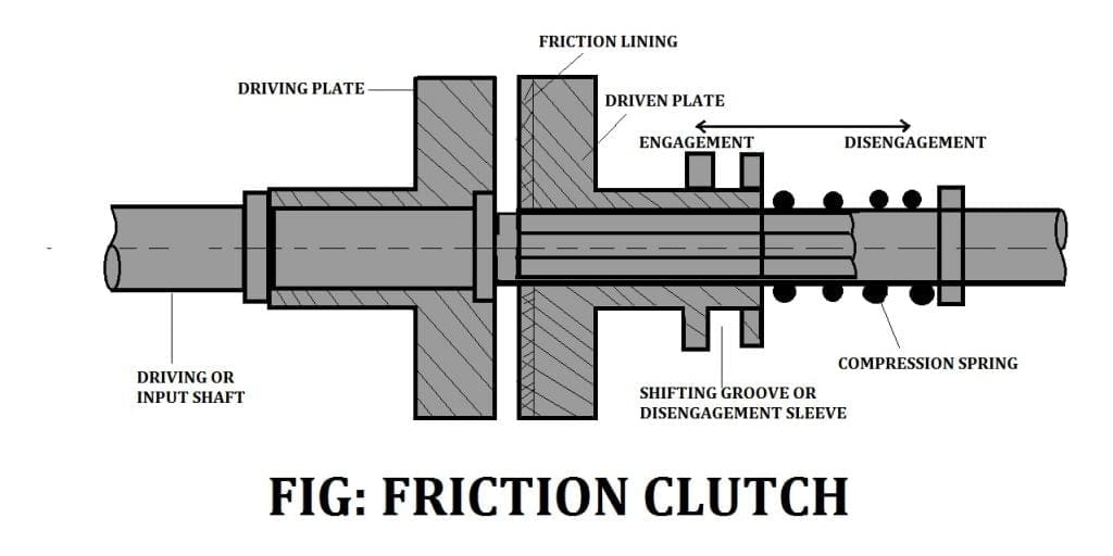
The friction clutch is another most important type. It is used to transmit the rotary motion of one shaft to another when desired. The axes of the two shafts are coincident.
The surfaces can be pressed firmly against one against when engaged and the clutch tends to rotate as a single unit.
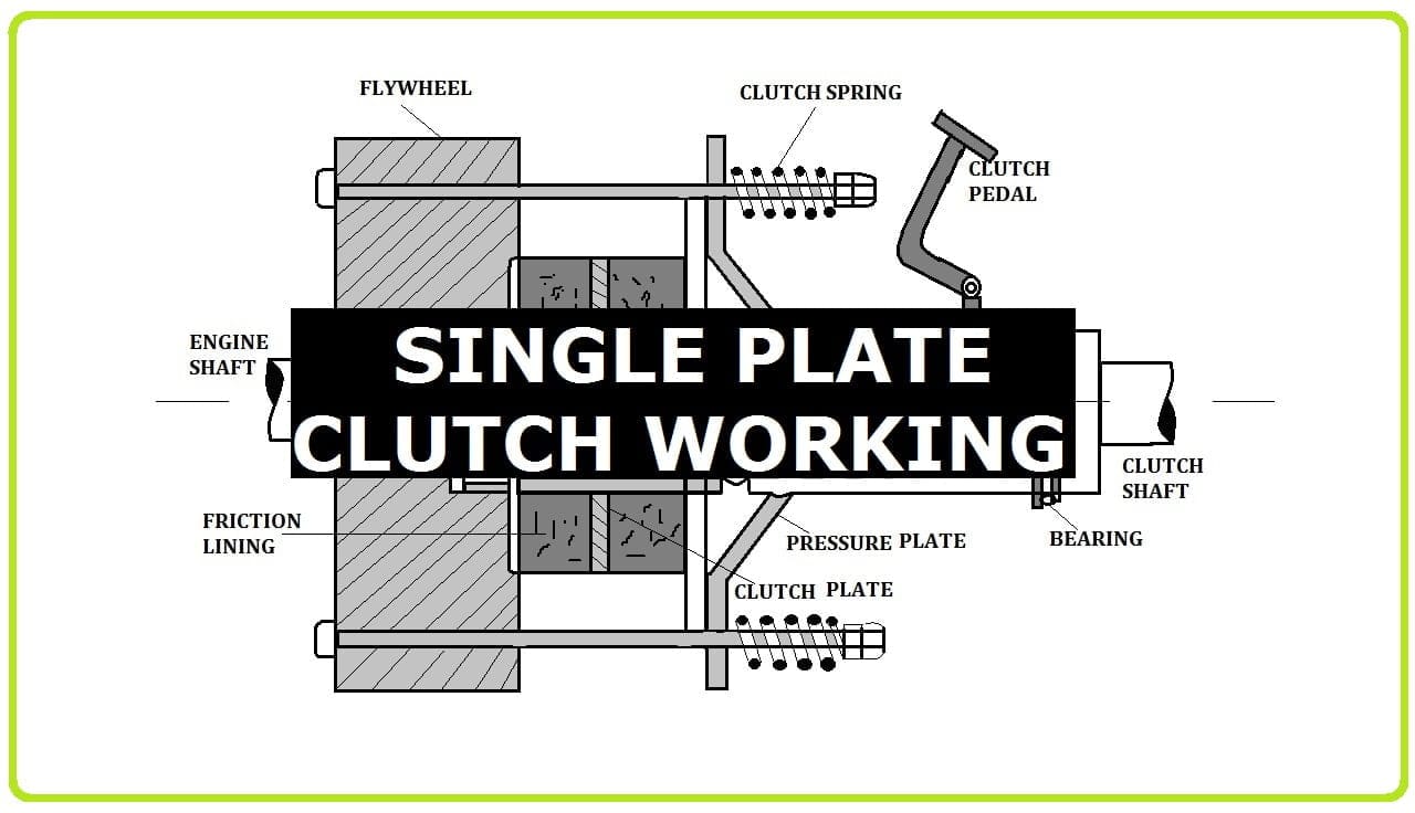
#3. Single Plate clutch:
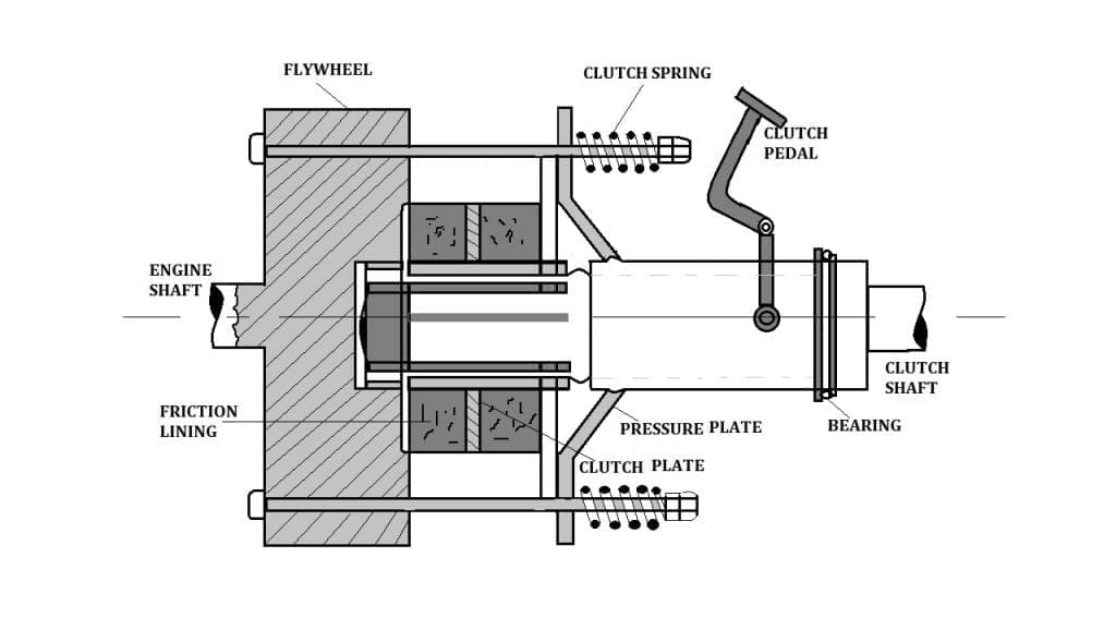
A disc clutch consists of a clutch plate attached to a hub that has splines cut on it and which is free to slide on splines cut on the driven shaft in the axial direction means parallel to the shaft.
The plate is made of metal generally of steel and has a ring of friction lining on each side which has large coefficient friction. The engine shaft supports a Flywheel.
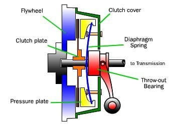
A spring-loaded pressure plate presses the clutch plate firmly against the Flywheel when the clutch is Engaged. the disengaged position, the springs press the cover attached to the Flywheel.
Thus both the Flywheel and the pressure plate rotate with the driving shaft. The movement of the clutch pedal is the movement of the pressure plate through a thrust bearing.
The pressure plate pulled by the release levers and the friction linings on the clutch plate is in no contact with the pressure plate or the Flywheel. The Flywheel rotates without driving the plate and thus, the driven shaft.
When we pressed off the foot from the pedal, the pressure on the thrust bearing is released. As a result, the springs become free to move the pressure plate to bring in contact with the clutch plate.
The plate slides on the splined hub and is gripped between the pressure plate and the Flywheel. The friction between the linings on the plate and the Flywheel on one side and the pressure plate on the other cause the clutch and hence the driven shaft to rotate.
In case the resisting torque on the driver shaft is more than the torque at the clutch, a clutch slip will occur.
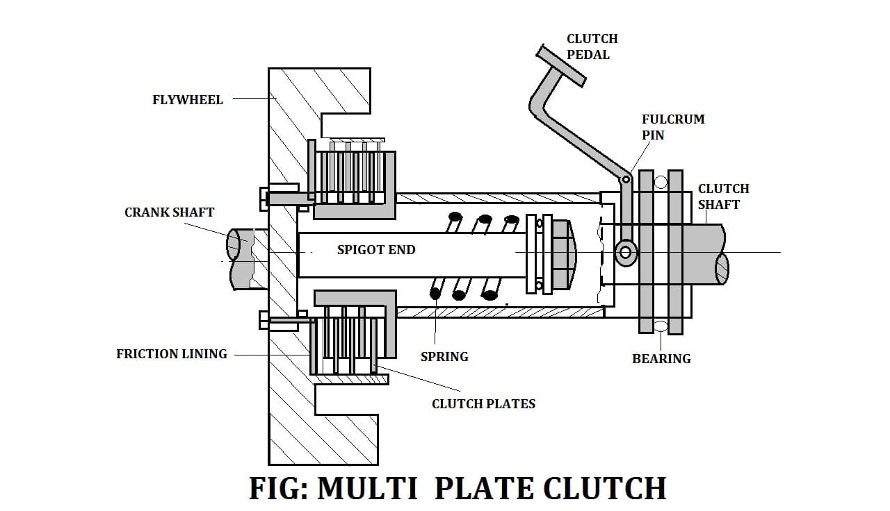
#4. Multi-Plate clutch:
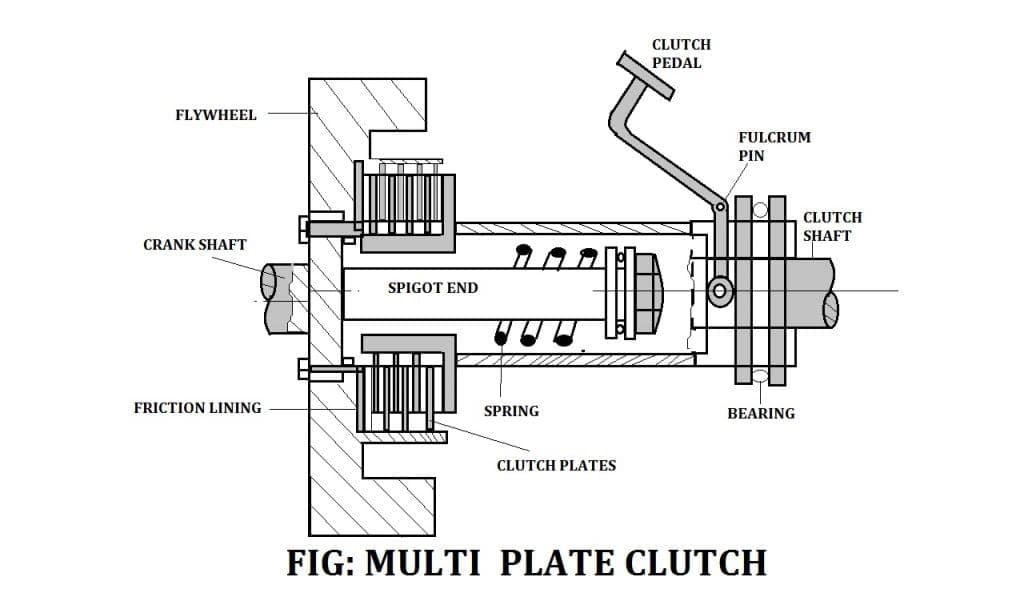
In the multi-plate, the number of frictional linings and the metal plates is increased which increases the capacity of the clutch to transmit torque.
Friction rings have splined on the outer boundary and Engage with corresponding splines on the Flywheel. They are free to slide axially. The friction material thus rotates with the Flywheel and the engine shaft. The number of friction rings depends upon the torque to be transmitted.
The driven shaft also supports the disc on the splines and them which rotate with the driven shaft and can slide in the axial direction If the adding force on the pedal is removed.
If n is the total number of plates both on the driving and the driven members, the number of active surfaces will be n-1 because 1 surface will be common.
#5. Cone Clutch:
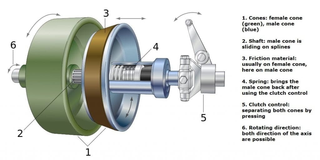
The contact surfaces are in the form of cones. In the Engaged position, the friction surfaces of the two cones are in complete contact due to spring pressure which will make in touch all the time. When the clutch is engaged.
If F is the axial Force, Fn is the normal force and £ is the semi–cone angle of the clutch then for a conical collar with uniform wear theory.
The main disadvantage of the Cone clutch is If the angle of the cone is made smaller than 200 the male cone tends to adhere to the female cone and it becomes difficult to disengage the clutch.
Cone clutch is used in low-speed applications and also used in ix engines and automobiles.
It is also used in very specialist transmissions in racing, rallying, or in extreme off-road vehicles. Cone clutches are used in powerboats.
#6. Centrifugal Clutch:
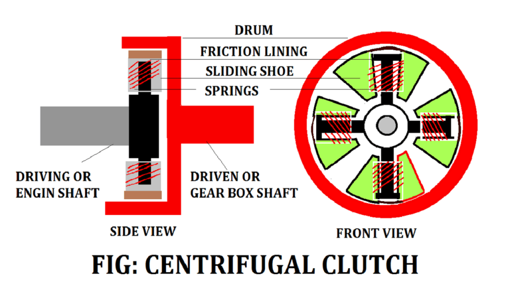
Centrifugal Clutches are being increasingly used in automobiles and machines. It has a driving member consisting of four slipping blocks and blocks kept by position means of flat springs for this purpose.
As the speed of the shaft increases, the Centrifugal force on the shoe increases.
The condition when centrifugal force more than the resisting force of springs, then the shoes will move forward and press against the inside of the rim and thus the torque is transmitted to the rim.
The only clutch is engaged when the motor gets sufficient speed to take up the load inefficient manner. The outer surfaces of the shoes are lined with some friction material.
On the input shaft, there are large extension springs, which connect to a clutch shoe. When driving spins fast enough, the springs extend causing the shoes to engage the friction face.
When the engine shaft reaches a certain RPM (Revolutions Per Minute), the clutch activates, working almost as it will gradually increase As the load increases the R.P.M. drops thereby disengaging the clutch and letting the RPM rise again, and reengaging the clutch.
This results in a fair bit of waste heat, but over a broad range of speeds, it is much more useful than a direct drive in many applications like mopeds and go-karts, etc. Weaker spring or heavier shoes will cause the clutch to engage at a lower R.P.M. while a stronger spring or lighter shoes will cause the clutch to engage at a higher R.P.M.
Advantages:
- Centrifugal has less maintenance.
- Not expensive.
- It does not need clutch pedal because it’s automatic.
- It helps to prevent the engine from stop running.
Disadvantages:
- Due to slipping and friction, there is a loss of power.
- It will transfer a high amount of power.
- It causes overheating problems.
- Its engagement and disengagements depend upon the speed of the driving shaft.
#7. Hydraulic Clutch:
This type of clutch use fluid means the use of hydraulics to transmit the torque. According to their design, this clutch is subdivided into two types:-
Fluid coupling:
It is a hydraulic unit that can be clutched in a semi or fully automatic mode. In this type of clutch, there is no mechanical connection between the driving member and the driven member.
A pump impeller is blotted on a driving member and engine a turbine runner is bolted on the driven member (Gearbox). Both the above unit is enclosed into single housing filled with liquid. This liquid will act as the torque transmitted from the impeller to the turbine. The driving member will start rotating then the impeller rotates and then by the liquid by centrifugal action in the outward direction.
This liquid then enters the turbine runner and exerts a force on the runner then flows back into the pump impeller, thus completing the circuit.
So the fluid coupling is not suitable for normal gearboxes which are used nowadays and it will be used with automatic and semi-automatic gearboxes.
Hydraulic torque converter:
A hydraulic torque converter has the same principle as that of the electric transformer.
The main purpose of the torque converter is to engage the driving member to driven members and increase the torque of the driven members. These all parts are enclosed into single housing filled with hydraulic liquid the impeller rotates with the driven member and it through the liquid outward by centrifugal action.
The difference of torque between impeller and turbine depends upon these stationary guide vanes. the hydraulic torque converter serves the function of the clutch as well as the automatic gearbox.
#8. Electro-magnetic clutch:
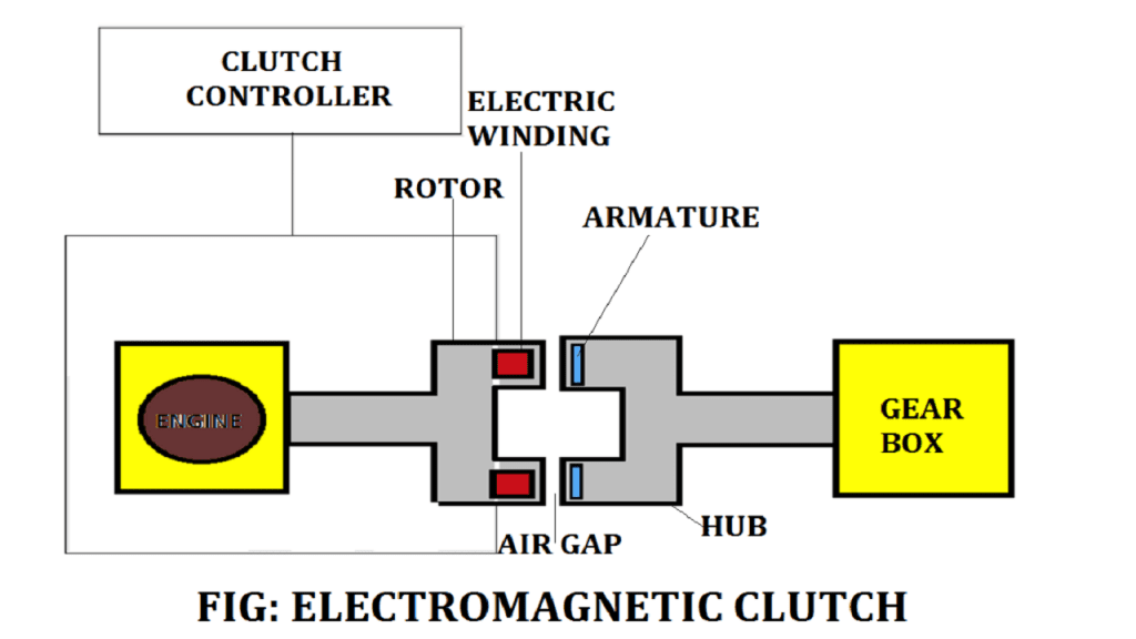
In the electromagnetic clutch, electromagnetism is used to exert a pressure force on one pressure plate to make the clutch engage. In this type, the driving plate is attached to the electric coils.
When the electricity is provided into these coils then the plate work as the magnet and it attracts another plate. So both plates join when the electricity provides and the clutch is in an engaged position. When the driver cuts the electricity, this attraction force disappears, and the clutch is in the disengaged position.
They should not be used for high speeds that have speeds over 50 rpm otherwise damage to the clutch teeth occurs when trying to engage the clutch.
How it works: When current flows through the clutch coil, the coil becomes an electromagnet and produces a magnetic line of flux. This flux is then transferred through the small gap between the field and the rotor.
The rotor portion of the clutch becomes magnetized and sets up a magnetic loop, which attracts the armature teeth to the rotor teeth.
When current is removed from the clutch field, the armature is free to turn with the shaft spring holding the armature away from the rotor surface when power is released creating a small air gap and providing complete disengagement from input to output.
#9. Hysteresis-Powered Clutch:
Electrical hysteresis units have an extremely high torque range. Since these units can be controlled, they are ideal for testing applications where varying torque is required. Torque which is a drag one is minimal that offers an available torque range for any Electromagnetic applications.
Since all torque is transmitted magnetically there is no contact so no wear occurs to any of the torque transfer components providing for extremely long life.
When the current is applied it creates magnetic flux this passes into the rotor portion of the field.
The hysteresis disk physically passes through the rotor without touching it. These disks have the ability to become magnetized depending upon the strength of the flux this means as the rotor rotates, magnetic drag between the rotor and the hysteresis disk takes place causing rotation.
When current is removed from the clutch, the armature is free to turn and no relative force is transmitted between either member. Therefore the only torque sees the input and the output is bearing drag.
Here is how the clutch works, when a DC voltage is applied to the Electromagnet coil a magnetic field is created.
The magnetic circuit passes through the clutch rotor and armature. The force is large enough to deflect the flat spring and the armature is pulled across a small air gap into the rotor face.
The friction between the rotor. When electrical power is removed from the coil the flat spring returns.
#10. Semi-Centrifugal Clutch:
It is used in racing car engines, high powered engines where clutch disengagements require appreciable and tiresome driver’s effort.
The power is transmitted partly by clutch springs and remains by the centrifugal action of an extra weight provided in the system.
11. Diaphragm Clutch:
In this type, springs are used instead of coil / helical springs. This type of clutch does not require any release levers as the spring itself acts as a series of levers.
12. Vacuum Clutch:
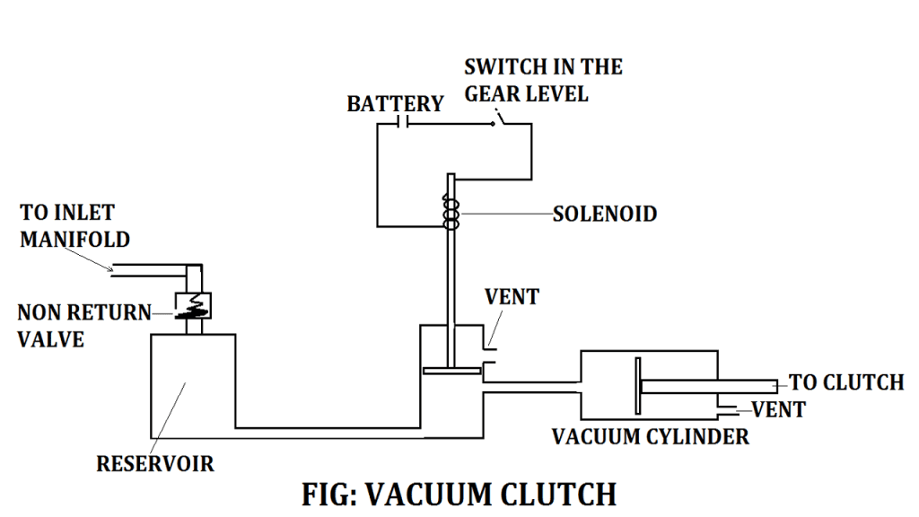
Vacuum clutch linkage operated by engine Vacuum created during suction stroke. This is consists of a vacuum reservoir tank that is connected to the engine inlet manifold through a non-return valve.
The reservoir is connected to a solenoid valve which is operated by a battery and switch in the gear lever and the control valve attached to the vacuum cylinder consists of a piston and plunger which are further connected to the release fork and release bearing.
Clutch Working Principle in Detail:
Clutch is used to attach two moving shafts that are moving at different speeds. This enables us to disengage the power of the engine and drive off smoothly with the engine.
When we press the pedal the friction disc which is movable slides on the shaft. This is the disengaged condition in which the friction doesn’t touch the Flywheel which means that the Axial load applied by the pressure plate is 0 and hence power/torque transmission is 0.
The engine is still running but the vehicle will not move.
When it is being pressed, the pressure plate moves back against the force of the springs, and the plate becomes free between the Flywheel and the pressure plate.
Thus the Flywheel remains rotating as long as an engine is running and the shaft speed reduces slowly and finally, it stops Rotating. As soon as the pedal is pressed the clutch is said to be disengaged. When we completely release the pedal the movable friction disc slides forward on that shaft.
This is an Engaged condition in which the disc has completely touched the Flywheel which means that the Axial load applied by the pressure plate is maximum and the spring force and hence power transmitted is max.
The plate is gripped between the pressure plate. Due to the friction between the Flywheel plate and pressure plate, the clutch plate revolves with the Flywheel.
As the plate revolves, the shaft also revolves. The shaft is connected to the transmission. Thus the engine power is transmitted from the crankshaft to the clutch shaft.
- One friction plate is bolted to Flywheel & the other is movable over the crankshaft.
- The amount of torque delivery depends on how much the Axial load is applied to the friction.
- The movable disc is splined on a crankshaft & is able to move back and forth with help of a pedal.
- More the Axial load more the power transmission less the Axial load lesser power transmission which also means If the load is zero, power transmitted will be zero and when the load will be max spring force power transmitted will be maximum.
- The load is applied by the pressure plate since the pressure plates are connected to springs which can multiple disc springs or a diaphragm spring.
- The main reason why we need a clutch is that it permits the engine to run even when the vehicle is not moving.
- Clutches have the ability to enable the driver and to change gears. This is important since changing gears without disengaging the clutch would apply sudden loads & shocks on gears which may ultimately result in failure of gears & transmission systems.
- To obtain smoothness white gaining or losing speed & to avoid engine shutdown.
- It plays a very important role to allow you to shift gears while moving in cars
Now while changing gears it is very necessary to break the transmission from the Flywheel to the gearbox for the proper shift of the gears to the gears to take place.
If this isn’t done the gears will be damaged and will need to be replaced by a new set of gearboxes. The role of the clutch takes place.
When we press the clutch it will get Engaged then it means the clutch breaks the contact with the Flywheel and hence, no drive is obtained from the engine. The gearbox can easily change gears with the help of synchronizers. Once the shift of gears is complete, we release the lever.
At this point, the clutch gets disengaged I.e, the clutch plate gets in contact with the Flywheel again. The drive is transmitted again to the gearbox.
When we pressed the padel then the pressure plate is pressed which is bolted with a Flywheel we applied force to the clutch cover inward then the disc will move upward and then the disc is separated from between flywheels and clutch disc.
A clutch as a verb is to hold or grasp something firmly it is a device that grasps one shaft to another shaft.
Internal combustion engines do not start from 0 rpm with some value of torque they need to run at least at an idle speed and will create more torque as the speed increases from idling when the load is at rest, and the engine is idling or faster, the clutch enables the spinning shaft to gradually transfer speed to the stationary shaft.
It transmits power from one element to another and it is a mechanical device. In an automobile, the engine is the prime mover.
A Flywheel is connected to the engine the clutch is connected to the transmission. driver press the clutch pedal, then the clutch plate is pressing the Flywheel.
Flywheel motion is transmitted to the transmission system. When the driver presses the clutch pedal the clutch is disengaged from the Flywheel so even if the engine gives rotation to Flywheel and it will not be transmitted to the transmission system that is why the driver presses the clutch pedal and changes the gear.
Clutch Working Video
Learn Engineering
Clutch Function:
The following function includes:
- It transmits power from the engine to the driving mechanism.
- Smooth transmission.
- Silent operation by reducing vibration due to driver operation.
- Protect drive train from engine jerks and vibrations
- The speed difference between an engine and a driven shaft by slip action will be removed
- The factor which must be taken into consideration in deciding what type of clutch is to be used are:
- Torque ( normal force, type of friction, surface, and a number of the surface), Rotation speed (light, compact, fast, slow, etc), Available space (diameter, height), Frequency of operation ( small travel, large travel, type of load, a simple engaging mechanism, large cooling area).
Clutch Application or Uses:
The simple application is to connect and disconnect two rotating shafts, one shaft is typically attached to a motor while the other shaft provides Output power. For example automobiles work while typically the motions involved are rotary but there can be linear clutches are also possible.
A Clutch is used to engage or disengage the engine in the gearbox. When the clutch is in an Engaged position, the engine power or rotary motion of the engine crankshaft is transmitted to the gearbox and then to the wheels.
When it is disengaged the engine power doesn’t reach to gearbox although the engine is running. It is also used to allow shifting or changing of gears when the vehicle is running for shifting gears clutch is first disengaged then gears are shifted and then the clutch is Engaged and It has to be disengaged to stop the vehicle and also at the time when we want to idle the engine or in an easy language neutral.
Clutch Advantages:
The following advantages of clutches are:
- The Engagement is smooth, with No heat generation unless the operation requires frequent starts and stops.
- Once engaged there is no slip.
- In some cases, it works as a safety device because it gets disengage when torque crosses the safety limits.
- Easy to operate.
- They are capable of transmitting partial power.
- Frequent engagement and disengagement are possible.
Clutch Disadvantages:
The following disadvantages of clutches are:
- The slip of the clutch can cause wear and tear.
Internal Resources:
- Single Plate & Multi-Plate Clutch
- Flywheel
- Camshaft
- Crankshaft
- Open Belt Drive vs Cross Belt drive
- Drum Brake vs Disc Brake
- Electronic Ignition System
- Lubrication System Types
- Magneto Ignition System
- Battery Ignition System
Reference [External Links]:
So here we finally studied Definition, Parts or Construction, Types, Working Principle, Functions, Advantages, Disadvantgaes, and Application in detail. I hope you have understood this topic. If yes then please share it with your friends and family.



Discussion about this post