A Slotter Machine is another machine tool similar to a Shaper or a Planer Machine. Today we will discuss Definition, Types, Main Parts, Mechanism, Operation, Specification, Application, Advantages, and Disadvantages with PDF of Slotter Machine.
Let’s start with the definition,
Slotter Machine Definition:
A slotter machine is a machine tool in which material is removed for producing desired shapes. It is used for producing Machining cylindrical surfaces and flat surfaces.
Now we will study types in detail,
Types of Slotter Machine:
The slotter machine can be classified into two types:
- Puncher Slotter Machine
- Precision Slotter Machine
Puncher Slotter Machine:
The puncher slotter is a rigid and heavier machine designed mainly for the removal of a large amount of metal from large castings or forgings. The length of the puncher slotter is sufficiently large which may be as long as 1800 to 2000 mm.
The ram of the slotter is driven by a spiral pinion meshing with the rack teeth cut on the underside of the ram and the pinion is driven by a variable speed reversible electric motor which is similar to the planer.
The feed is also controlled by electrical gears.
Precision Slotter Machine:
It is a simple and lighter machine. It is operated at high speeds and the machine is mainly designed to take light cuts for accurate surface finish.
The machine can handle a number of identical works on a production basis by using special jigs. These machines are fitted with a whit worth quick return mechanism.
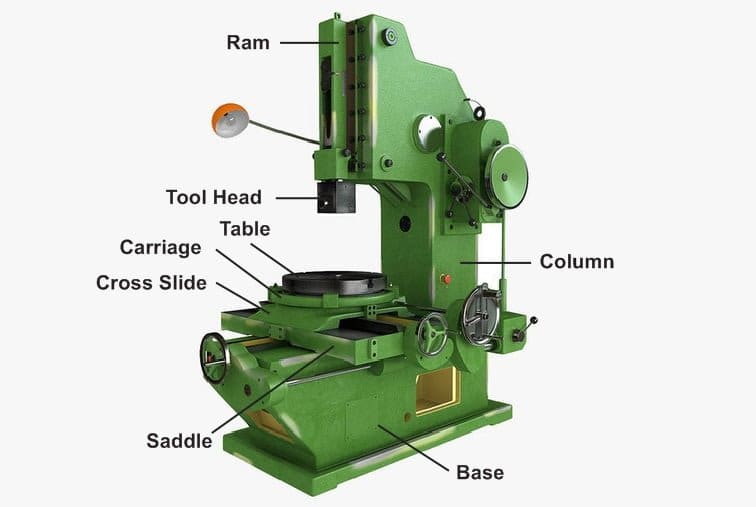
Slotter Machine Main Parts or Construction:
Slotter Machine consists of following Main Parts:
- Base
- Column
- Saddle
- Cross-slide
- Rotating table
- Ram and Tool head assembly
- Ram drive mechanism
- Feed mechanism

Base or Bed:
It is a rigid cast iron casting built to take up all the cutting forces and the entire load of the machine.
The top surface of the bed is accurately machined to provide guideways on which the saddle is mounted and slides. These guideways are perpendicular to the column face.
Column:
It is a vertical member and cast integral with the base. Column houses the ram driving and feeding mechanisms.
Accurately machined guideways are provided on the front face of the column on which the ram is made to reciprocate.
Saddle:
The saddle is box-like casting mounted over the guideways on the bed surfaces and it moves toward or away from the column and either by hand or power control to give the longitudinal feed to the work.
The top surface of the saddle is provided with accurately machined guideways perpendicular to the guideways on the bed for moving the cross-slide.
Cross-slide:
It is mounted over the saddle guideways and made to move parallel to the column face. The movement of the slide may be controlled either by the power to give the cross feed.
Rotating or Rotary table:
The slotter is provided with a circular table mounted on the top of the cross slide. It can be rotated by rotating the worm which meshes with a worm gear connected at the underside of the table.
The table may be graduated in degree for indexing or dividing the periphery of the jobs.
T-slots are cut on its top surface for holding the work by clamping devices. The rotation of the table may be effected either by hand or power.
Ram and Tool head assemble:
The ram is mounted on the guideways of the column and reciprocates by holding the tool at its bottom end of the tool head.
Slotter Machine Mechanism:
Following are the slotter machine ram drive mechanism:
- Whitworth quick return mechanism
- Variable speed reversible motor drive mechanism
- Hydraulic drive mechanism
Whitworth Quick Return Mechanism:
A simple whit worth quick return mechanism as shown in the figure.
The bull gear is mounted on a fixed hub at the rear end of the machine and it is rotated by a driving pinion from the motor.
The driving plate is connected to the main shaft through the fixed hub.
It holds the crankpin with a sliding block and slides on a driving plate. So that when bull gear rotates, imparts rotary motion to the driving plate and shaft causing the disc to rotate at the end of the main shaft.
The disc is connected to the lower end of the connecting rod eccentrically by means of a pin in a radial T-slots on the face of the disc, which converts the rotary motion of the disc into reciprocating motion of the ram connected to the top end of the connecting rod.

The principle of quick return mechanism can be explained simply by a line diagram as shown in the figure.

A and B are the fixed centers of the bull gear and the driving plate. The crankpin and the slide block rotate in a driving plate about B.
This causes the disc to rotate through the main shaft. The pin 3 on the disc rotates in a circular path about the fixed point B.
The length of the ram is equal to twice the throw of eccentricity and it is equal to 2*3B (3B= throw of eccentricity).
When the slide block is at c, the ram is at the maximum upward position of the stroke and when it is at, the ram is at the maximum downward position.
If the bull gear rotates in the anticlockwise direction and the slide block rotates through an angle CAD, the ram performs downward cutting stroke, whereas when the block rotates through an angle DAC, the ram performs return stroke.
As the block rotates at a constant speed the rotation of slide block through an angle CAD during cutting stroke takes a longer time than the rotation through an angle DAC during the return stroke.
Thus the quick return motion is obtained.
The stroke length of the ram can be changed by altering the position of pin ‘3’ on a disc with respect to the center ‘B’.
The stroke position of the ram can be adjusted by releasing the nut and then altering the position of the connecting rod on the body of the ram and then the nut is tightened again.
As the ram moves in a vertical axis, the weight of the ram is counterbalanced by a counterbalancing weight.
Feed Mechanism:
In a slotter, the feed is given by a table either by hand or power.
The slotter table may have three movements:
- Longitudinal feed: If the table is fed perpendicular to the column toward or away from its face is known as a longitudinal feed.
- Crossfeed: If the table is fed parallel to the face of the column is known as crossfeed.
- Circular feed: If the table is fed by rotating the table about the vertical axis is known as a circular feed.
Power (Automatic) Feed Mechanism:
The power feed mechanism as shown in the figure.

It consists of a bull gear with a cam groove in which a roller side.
When the bull gear rotates, the roller attached to the lever follows the contour of the cam groove and moves up and down only during a very small part of the revolution of the bull gear.
The cam groove is so cut that the movement of the lever will take place only at the beginning of the cutting stroke.
The rocking movement of the lever is transmitted to the ratchet and pawl mechanism so that the ratchet will move in one direction only during a short period of time.
The ratchet wheel mounted on a feed shaft may be engaged with a cross, longitudinal or rotary feed screws individually or together it gives the feed movement to the table.
Types of Slotter Machine Operation:
The following operations are performed in a slotter machine are:
- Machining cylindrical surface.
- Machining flat surface
- Machining irregular surface and cam machining
- Machining slots, keyways, and grooves.
Specification of Slotter Machine:
The size of the slotter machine can be specified by the following specification:
- Maximum stroke length of the ram.
- The diameter of the table.
- Amount of cross and longitudinal travel of the table.
- The number of speeds available.
- The number of feed available.
- Horsepower of the motor
- Type of quick return mechanism
- Floor space is required
- Net weight of the machine
Application of Slotter Machine:
The following application of slotter machine is:
- It is used for cutting keyways,
- Grooves and slots of various shapes,
- For making regular and irregular surfaces both external and internal,
- Cutting internal and external gears,
- For holding large, awkward jobs.
Advantages of Slotter Machine:
The advantages of slotter machine are:
- Slotter machine is a light machine comparatively other machine tools.
- The price of a machine is not so high.
- Low maintenance required.
- The machine produces a good surface finish for a workpiece.
Disadvantages of Slotter Machine:
The disadvantages of Slotter Machinis that The worker should have knowledge of machine to operate and second one is the machine construction is not simple.
Differences Between Shaper and Slotter Machine:
It operates on the same principle as that of a shaper but in shaper, ram holding the tool reciprocates in a horizontal axis whereas, in slotter, the ram holding the tool reciprocates in a vertical axis.
The slotter and vertical shaper are almost similar but in a vertical shaper, the ram holding the tool can reciprocate at an angle to the horizontal in addition to the vertical stroke and the ram can also be swiveled not more than 5 degrees to the vertical, whereas in slotter it is not possible.
So this is all about Slotter Machine from my side. Let me know what else I can help you with this topic.

Discussion about this post