The orifice Meter is a topic of fluid machinery and it is a device that is used to measure the flow rate or average velocity of the flowing fluid (Liquid or gases) in a pipe.
Here the orifice plate is used for the restriction in the direction of the fluid flow. Therefore the restriction process we also called Orifice Plate. The restriction effect results in pressure drops of the flowing fluid.
The drop in pressure is associated with the rate of flowing fluid or the average velocity of the fluid.
Now lets see definition,
Orifice Meter Definition:
The orifice Meter or Plate can be defined as the device in Fluid Mechanics and machinery which is used for measuring the flowing fluid rate or in other terms the average velocity. The orifice meter or Plate works on the principle of Bernoulli’s theorem and that is the sum of all the energy at a point is equal to the sum of all the energy at point 2.
Orifice Meter or Plate Types:
There are 4 different types that include Eccentric, Conical, Sharp Edge, Segmental, and Quadrant Orifice Plate.
Eccentric Orifice Plate:
It is used for measuring fluids who carry small amount of or gases with small amounts of liquid and non-abrasive solids. It has a round opening (bore) tangent to the inside wall of the pipe.
Conical Orifice Plate:
Conic Edge orifice plate is useful for lower Reynolds numbers. It has a 45° bevel facing upstream into the flowing stream.
Segmental Orifice Plate:
The segemental plate is also used for measuring fluids that is liquid or gases carry non-abrasive impurities such as light slurries or exceptionally dirty gases.
Quadrant Orifice Plate:
This orifice is used for high viscosity Fluids.
Now moving to construction,
Orifice Meter Construction or Parts:
Orifice Meter Consists of following four Parts:
- Inlet Suction
- Orifice Plate
- Flow Conditioner and
- Outlet section

Inlet Section:
The name inlet section means the fluid will enter into the orifice meter through the inlet section.
Orifice Plate:
The orifice plate is situated between the inlet and outlet and the plate is used to generate pressure drop that will enable the flow rate. The orifice plate construction: It is thin size having one hole from that the water will pass.
Flow Conditioner:
The flow conditioner is used to increase the linear flow in the inlet section of the meter tube. The flow conditioner is installed nearly the inlet section of the meter tube.
Outlet Section:
Now Here in the outlet section, the pressure of the fluid is being discharged and determined.
Orifice Meter Working Principle:
The working of the orifice meter is based on the principle of Bernoulli’s equation.

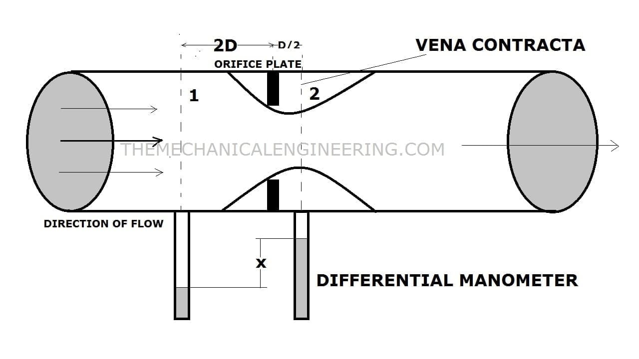
As you can see in the diagram there is a pipe in which fluid is passing from one side to another side that is an inlet to outlet. The manometer is attached hereto measure the pressure differences between two-point.
Now we place an orifice plate which is thin in size and having a small hole in between through which the fluid will pass. Now when the increases in the velocity, the decrease in the pressure and it is vice versa.
The place of the orifice plate in the pipe only determines the flow rate or discharge at that point only. The discharge can be calculated by the formula and that will be explained in the derivation section.
Orifice Meter hydraulic coefficient:
There are four hydraulic coefficient of Orifice meter and those are:
- Coefficient of Contraction
- Coefficient of Velocity
- Coefficient of Resistance
- Coefficient of Discharge
Coefficient of Contraction:
Coefficient of contraction can be defined as the ratio of the area of the jet at vena contracta to the area of Orifice.
Coefficient of Velocity:
Coefficient of discharge can be defined as theratio of actual velocity of jet at vena contracta to the theoretical velocity of the jet.
Coefficient of Resistance:
Coefficient of resistance can be defined as the ratio of loss of head in the orifice to the head of water available at the exit of the orifice.
Coefficient of Discharge:
The coefficient of discharge can be defined as the ratio of Qact (actual discharge) to the Qthe (theoretical discharge).
Now our main topic derivation,
Orifice Meter Derivation or Experiment:

As you can see in the diagram,
d1= Inlet section diameter
P1= Inlet section pressure
v1= Inlet section velocity of the fluid
A1= Inlet section Area
d2= Outlet section diameter
P2= Outlet section pressure
v2= Outlet section velocity of the fluid
A2= Outlet section Area
Cd= Coefficient of discharge
There are some assumption to derive orifice meter discharge and that is
- Fluid must be ideal
- Fluid flow irritation. steady and continuous
- The inner surface must be frictionless
Bernoulli’s Therom: In an ideal that is an incompressible fluid, the sum of all pressure energy, kinetic energy, and Potential energy is equal in section 1 will be the same as in section 2
Now applying the Bernoulli’s equation in this at point 1 and 2:
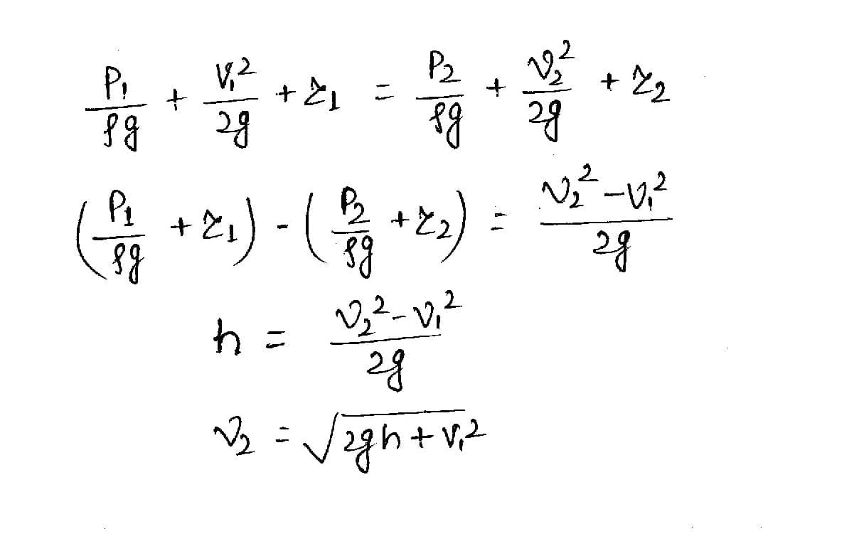
Here h is the differential head.
And A0 is the area of orifice and Cc is coefficient of contraction. Cc=A2/A0
Now the continuity equation which is A1v1=A2v2

Therefor the discharge is,
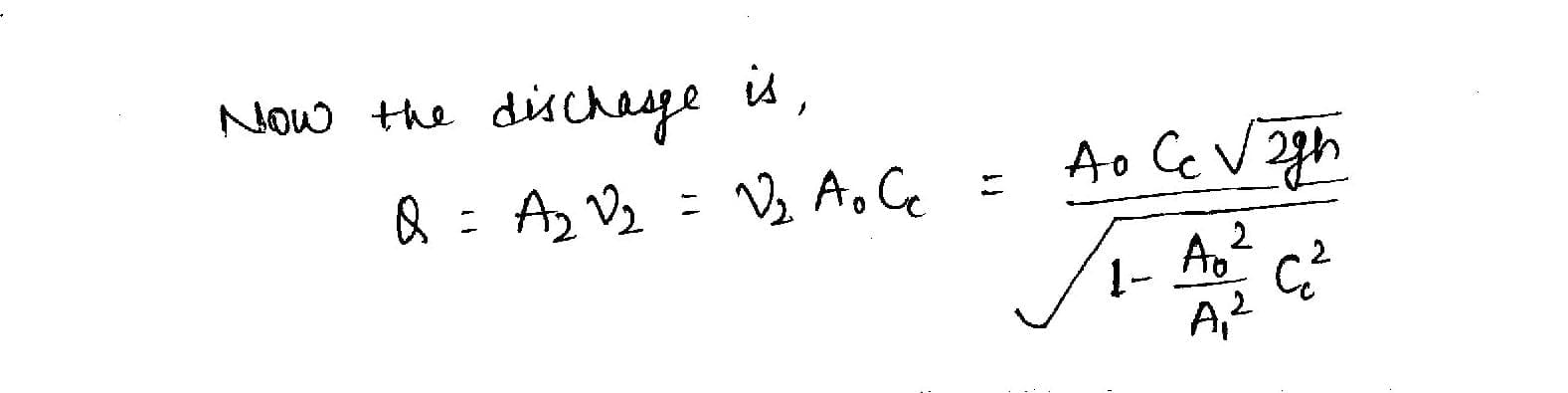
If Cd is the coefficient of discharge for orifice meter then,
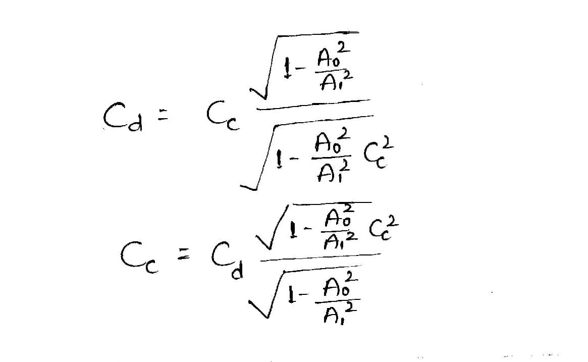
Now the above equation we will use the Cc value in the discharge Q therefore we will get the value of discharge is,
Here the Cd value will be low as compare to Cd value of Venturimeter.
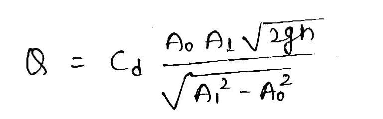
Orifice Meter Formula:
From the below formula you can easily calculate the actual discharge of Orifice Meter.

Orifice Meter Specification:
The specification of orifice Meter or Plate is:
- The length of the Orifice can be from 10 mm to 800 mm.
- The diameter of the orifice plate can be 0.5 times the diameter of the pipe though it may vary from 0.4 to 0.8 times.
- Up to 800 degrees celsius Operating Temperature.
- The Operating Pressure is up to 400 bar.
Orifice Meter Advantages:
The following advantages of Orifice meter is:
- The Orifice meter is very cheap compared to other flow meters like the venturi meter and so on.
- The direction possibility can be vertical, horizontal, and inclined.
- The space required for installation is less.
- It is usually thin enough to fit between an existing pipe.
- The maintenance cost is low.
- It offers very less pressure drop.
- The construction and design of this orifice meter are very simple.
- It is capable to determine a wide range of flow rates that the main advantages.
Orifice Meter Disadvantages:
The following disadvantages of Orifice Meter is:
- Due to limitations in the vena-contracta length, the minimum pressure for reading the flow is sometimes difficult.
- In the Venturi meter, downstream pressure can be recovered. But In Orifice meter downstream pressure can not be recovered in Orifice Meters.
- It requires a single phase of liquid.
- The orifice Accuracy can be affected by the viscosity, density, and pressure of the fluid.
- It requires a straight pipe for good precision and accuracy.
- The 40% to 90% overall head loss of the differential pressure.
- The obtained coefficient of discharge is low.
Orifice Meter Application:
The main application of orificemeter is used at several places to measure flow rates such as Water Treatment Plants, Natural Gas, Petrochemicals, Oil Filtration Plants, and Refineries.
Internal Resources:
Pump vs Compressor
Francis Turbine
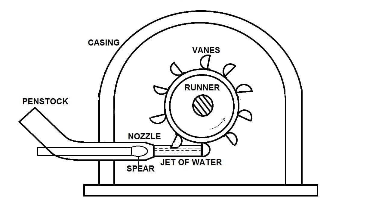
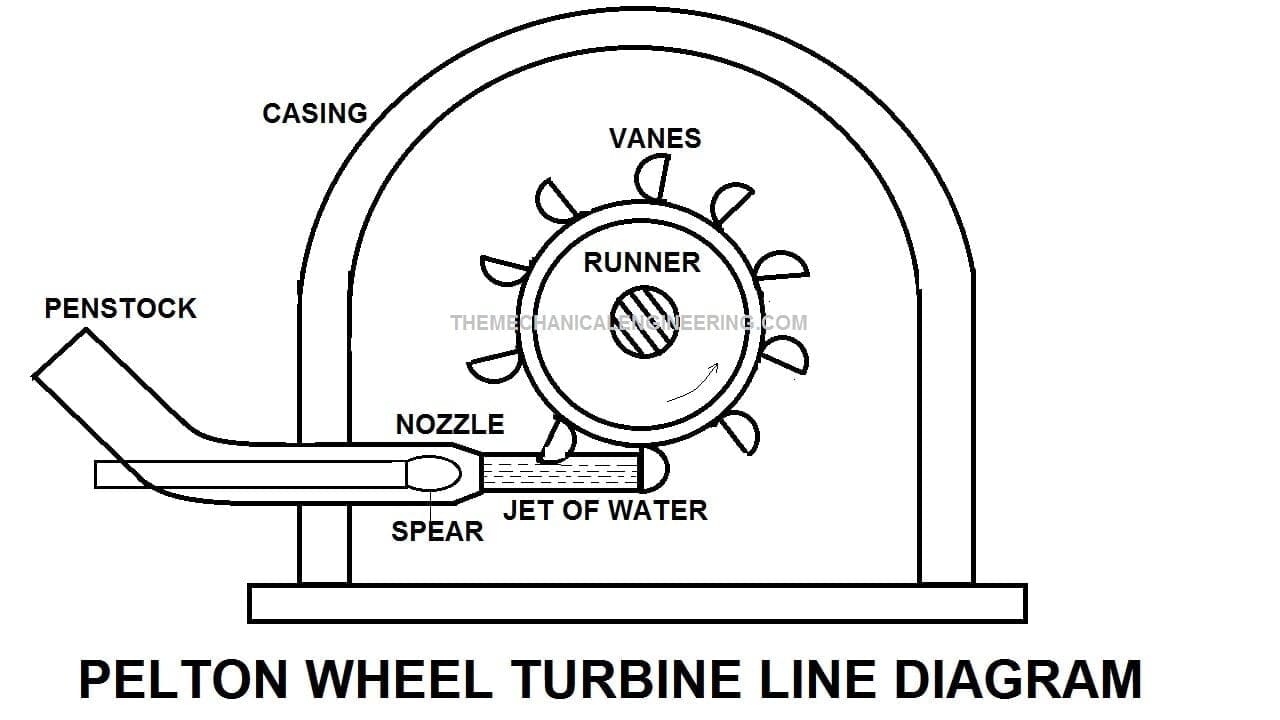
Pelton Wheel Turbine
Types of Fluid Flow
So finally our article ends here. I have also explained another flow meter that is the venturi meter you can read that too. And if you like the article then do not forget to spread the love.


Discussion about this post