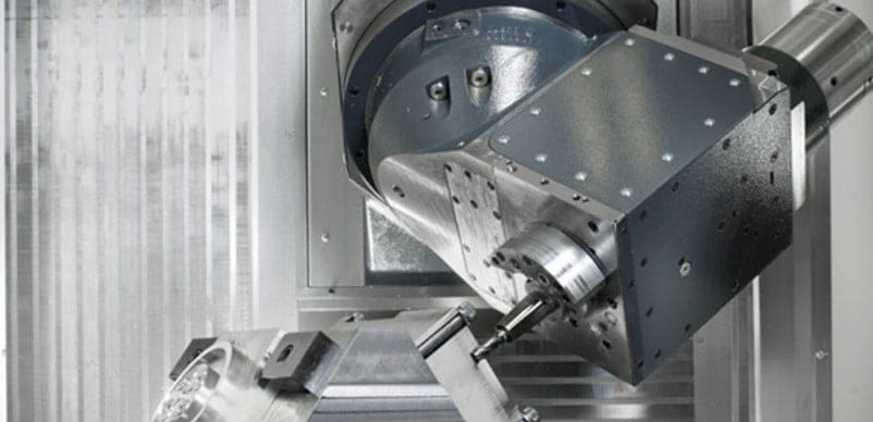
The milling cutter is the tool used in the Milling Machine for performing several operations.
In this article, we will study the Types and Materials of Milling Cutter.
At the end of the article, you can download the whole article in PDF format.
Milling Cutter Definition:
The milling cutters are the most important part of the machine which is used for the removal of the material from the surface of the workpiece. The availability of a large variety of the milling cutter makes it the most versatile machine used in the industries.
Now let’s dive to Cutter Types in Detail,
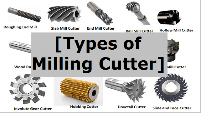
Milling Cutters Types:
The various type of Milling cutters are:
- End Milling cutter
- Peripheral Milling cutter
- Side Milling cutter
- Straddle Milling cutter
- Gang Milling cutter
- Staggered Milling cutter
- Concave Milling cutter
- Cylindrical Milling cutter
- Hollow milling cutter
- Woodruff cutter
- Thread milling cutter
- Hobbing cutter
- Dovetail cutter and
- Ball milling cutter
Now let’s discuss one by one in brief:
1. End Milling cutter:
End mill cutters are the type of cutters used in the milling which has teeth at the end or at the face of the circular disk. This type of cutter is mostly used with the vertical mill machine.
An end mill cutter should be selected which has the geometry and cutting-edge angle compatible with the job (workpiece) being machined so as to minimize side thrust, avoid tooth and shank breakage, minimize wear and maximize the material removal rate.
2. Periphery Milling Cutter:
When the cutting teeth are present on the periphery of the circular disk then it is known as periphery mill cutter.
Periphery Mill cutter can only be used for the Horizontal mill machine.
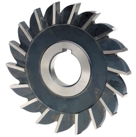
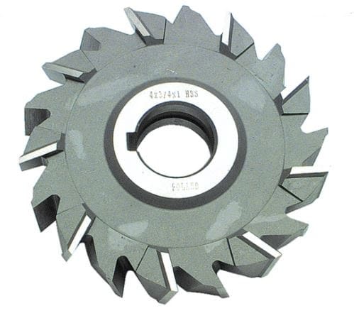
3. Side Milling Cutter:
Side Mill cutter is a type of cutter in which the cutting teeth are present on the periphery and also at the face or end.
This cutter is mostly used in straddle Milling operations and face Milling operation. It is also used for cutting slots and milling deep and narrow slots.
4. Face Milling Cutter:
Face mill Cutter consists of a large diameter cutter body with a number of mechanically fastened inserted tools. By making radially deep and axially narrow cuts a large volume of the material is removed.
The diameter of the cutter body depends upon the length of the workpiece and the clearance available on either side of the workpiece.
Face Mill cutters are used in the down Milling. Face Mill cutter is very rigid and the surface finish depends upon the feed rate and the number of teeth.
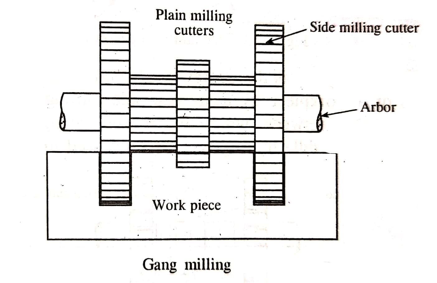
5. Gang Milling cutter:
It is a type of cutter in which the peripheral milling cutters of the different sizes are cut together to remove the material simultaneously from the workpiece.
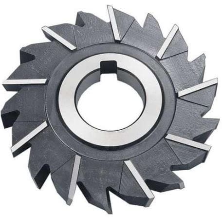
6. Staggered Mill Cutter:
Staggered Mill cutter has their teeth staggered at the periphery with alternate right-hand and left-hand helix angles and are made in relatively narrow width.
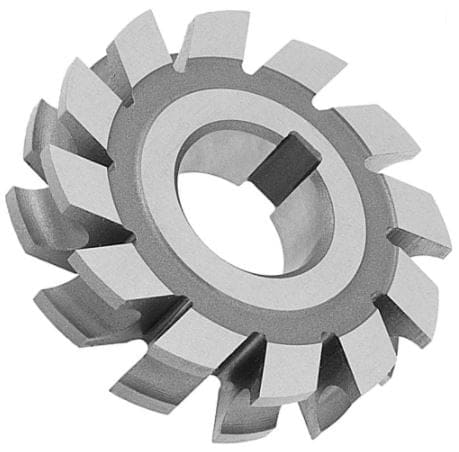
7. Concave Milling Cutter:
The concave cutter is a type of formed cutter. Formed Cutter is designed to produce a specific shape on the workpiece.
Concave Milling Cutter is a type of cutter which is shaped to mill a convex surface of circular contour equal to half a circle or less.
8. Cylindrical Milling Cutter:
Cylindrical Mill Cutter is the type of cutter which has a cylindrical shape and has teeth on the circumferential surface only.
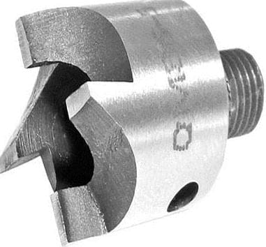
9. Hollow milling cutter:
It looks like a pipe having thicker walls. The cutting teeth of the hollow mills on the inside surfaces. This cutter used in the screw machines.
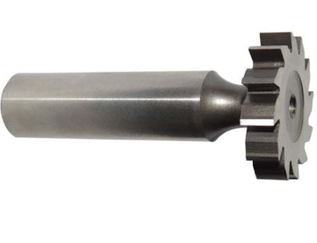
10. Woodruff cutter:
This tool used to cut the keyway for a woodruff key. It is slightly hollow-ground on the sides for relief and the teeth are not side cutting. The teeth come in both straight and staggered varieties.
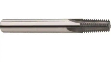
11. Thread mill cutter:
The thread is produced by doing a helical interpolation. The cutting process enables the production of threads from a nominal diameter of 1 mm (single profile), with multi-profile from M2.
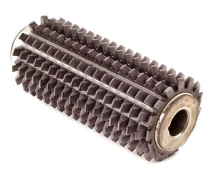
12. Hobbing cutter:
It is also is a cutting tool used to cut the teeth into the work piece. This is cylindrical in shape with helical cutting teeth.
13. Dovetail cutter:
The dovetail cutter is an end mill whose form leaves behind a dovetail slot.
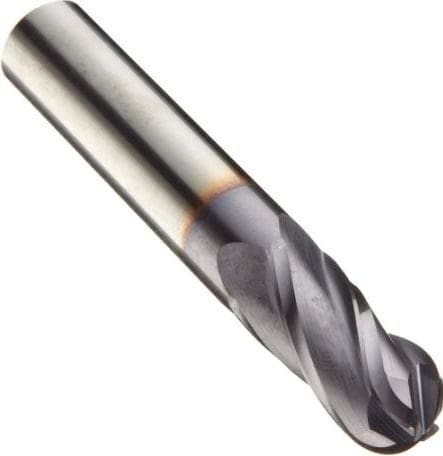
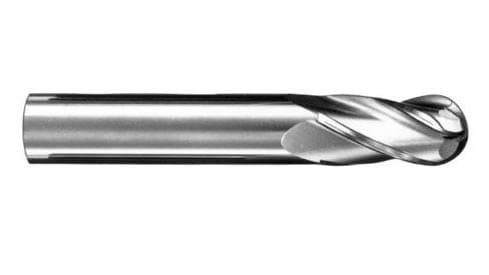
14. Ball cutter:
It is also called as ball nosed cutters. Ball cutters as their end are hemispherical in shape. It is used to decrease stress concentration. It is also used for cutting three-dimensional shapes.
Milling Cutter Animated Video:
Brief Geometry of the Milling Cutter:
The five important angles involved in the making of the millcutter are:
- Radial Rake Angel: The radial Rake angle of the milling cutter is equal to the side rake of the single point tool.
- Axial Rake: The axial Rake angle of the cutter is equal to the Back Rack of the single point tool.
- Radial Relief.
- Axial Relief: If the radius of the cutter lies along the face of the mill cutter then it is said to have a zero Rake.
- Clearance Angle: The angle between a line through the surface of the land and a tangent to the periphery at the cutting edge.
Some Important Point on Clearance Angle:
- A clearance angle is given to prevent the back of the tooth from rubbing against the workpiece.
- Generally, cutters having a diameter above 75mm will be given a clearance of 3 to 5 degrees.
- In the case of the small diameter cutters, a large clearance angle is given to eliminate the tendencies for teeth to rub against the job(workpiece).
Clearance angle also depends upon the work material like for,
- Cast Iron (C.I): The clearance angle for the cast iron is 4 to 7 degrees.
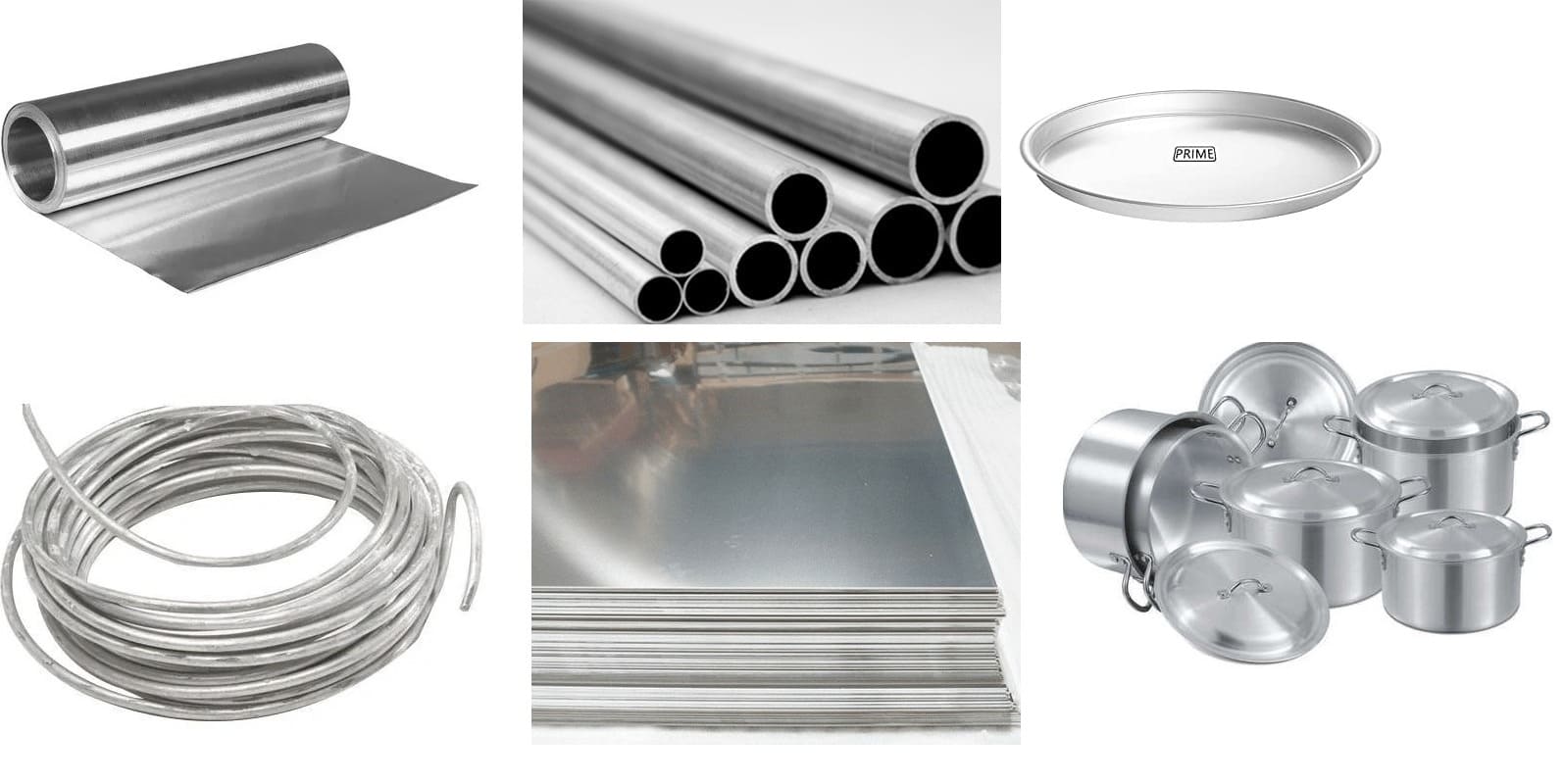
- For soft Metal like Mg, Al, Brass the clearance angle is 10 degrees to 12 degrees.
Milling Cutter Material:
Material used for making up of the milling cutters are:
- High Carbon Steel.
- High-speed steel.
- Sintered carbide tip.
- Stellite.
Out of all the above four mentioned material for the used for the making of the cutter, High Carbon Steel is less used because the cutters made from it get dull quickly if high cutting speed and feed are used.
Various grades of Highspeed steel are used extensively for the making of the cutter because they maintain a keen cutting edge even at high temperatures and thus can be easily used at high speed.
Precautions should be followed when the use of Metal cutter in Milling Machine:
The various precautions which should be followed while using a metal cutter are as follows:
- It should be stopped before setting up or removing the metal cutter or workpiece or any other accessories.
- In case if the cutting teeth are dull, then they should be sharpened using a cutter grinder.
- Bur should be removed from the mill cutter before using it for further milling process.
- All the chips should be removed from the cutter before using it for new milling work.
- The cutting speed, feed, and cutting fluid should be most appropriate for the material, cutter, and milling process.
- The cutter when should be stored properly in the racks. It should be ensured that the teeth do not hit other cutters or metal parts.
- The workpiece and cutter should be kept as cool as possible and the cutter should be rotated in the right direction only.
So Here we studied all the types and Material of Mill Cutter.
Reference [External and Internal Links]:
Related Articles:
Milling Machine
Lathe Machine
Cutter Definition

Discussion about this post