The first camshaft was described by an Islamic engineer Al-Jazari in 1206 in an automated water-raising machine.
As per automobiles are concerned Maudslay was the first car to use single overhead camshafts which were designed by Alexander Craig. These were also used in Marr auto cars in 1903 which was designed by Michigan.
In this article, we will study the Definition, Function, Construction, Working Principle, Types in detail, Advantages, Disadvantages, and Application in detail. And at the end, you can download a PDF version of it easily.
What is definition of a Camshaft?
A camshaft is a mechanical device used in an IC engine to perform the opening and closing action of the inlet and exhaust valve at the right time. The basic function is to convert rotatory motion into linear motion.
As we know that in an internal combustion engine it is very important that the fuel should come into the cylinder at the right time and the exhaust gases should also leave the cylinder at the right moment of time. This function is accomplished with the help of a camshaft. A camshaft achieves its motion either independently or by the engine crankshaft.
The function of camshaft:
The following three functions are:
- It promotes the opening of the inlet valve during the suction stroke.
- The second function is to open the exhaust valve during the exhaust stroke.
- Lastly, It keeps both the valves closed the rest of the time.
Now we will study construction in detail,
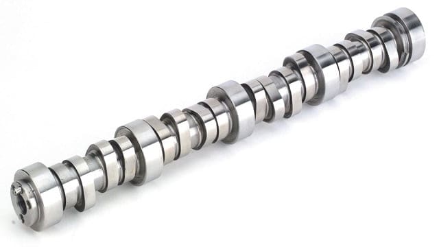
Construction of Camshaft:
The main parts involved in the construction of the camshaft are:
- Driveshaft
- Shaft
- Bearings
- Cam
- Lobes
- Thrust plate
- Chain sprocket and
- Woodruff key
We will study one by one in detail.
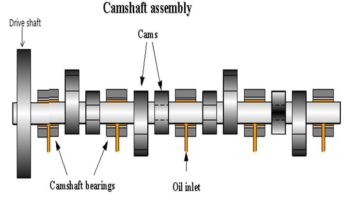
Driveshaft:
This is the part of the camshaft that provides motion to the whole assembly is called a drive shaft. A drive shaft is either connected to the crankshaft with a belt or is operated independently. In most cases, it is connected with the crankshaft.
Shaft:
The supporting structure which holds all the other components is called a shaft. It is designed to withstand high fatigue loads when the engine is running.
Bearings:
Bearings are very important elements of it as it holds the shaft in the correct position and also reduces frictional losses during the operation of the camshaft. It is also provided with an oil inlet for a constant oil change in the camshaft.
Cam:
Cams are the main parts of the assembly. A cam is so designed that it keeps the valves closed all the time and opens it by pushing it at the right moment. A cam and follower set are discussed later in the article.
Lobes:
The main working of lobes is to open and close the valves for intake and exhaust gases. The speed of the lobe depends on the current engine speed.
Thrust plate:
As you can see in the diagram The thrust plate is on the right side and it is attached between the cam and timing gear. The thrust plate is mounted on the front cover for proper end play.
Chain sprocket:
It is attached to one end of the camshaft in a combustion engine. This sprocket, along with the timing belt and the crankshaft sprocket, is responsible for maintaining the timing between camshaft and crankshaft.
Working of camshaft:
Before understanding the working of the camshaft, it is necessary to understand the working of cam and follower arrangement which is also the principle behind the working of automobile camshaft.
Working principle:
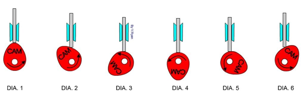
The figure shows different stages of cam and follower. The cam is not circular in shape hence when rotated it lifts the follower up and down. In diagram one, the peak of the cam has lifted the follower to the fullest. As the cam rotates in an anticlockwise direction the follower drops down a then again starts rising after the cam has moved by 180 degrees.
Working of the camshaft in an IC engine
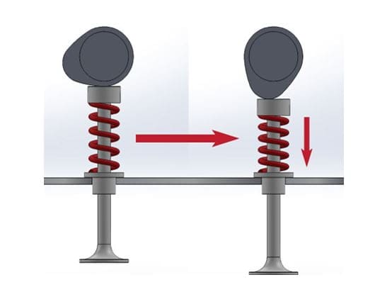
The figure shows the actual operation of a camshaft in an internal combustion engine. The valve is closed in figure 1. As the cam rotates due to the rotation of the drive wheel, it pushes the valve against the spring and thus opening the valve in the next figure. As soon as the operation (fuel inlet or exhaust gas outlet) is done the spring forces the valve back to its original closed position.
Types of camshafts:
There are two types of camshafts:
- Single overhead and
- Double overhead camshaft.
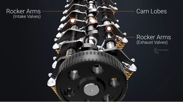
Single overhead camshaft:
A single overhead camshaft is often referred to as SOHC. As the name suggests a single overhead uses only one shaft with multiple cams to operate input and exhaust valves.
In the case of SOHC, there is a need to use a rocker arm to perform the opening and closing of the valves.
It was an earlier designed camshaft. It provides better torque at mid-RPM.
Simple design leads to ease of understanding. There is a place for the spark plug to be placed as the camshaft is placed in between the two cylinders.
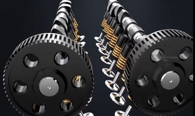
Double overhead camshaft:
A double overhead camshaft is also commonly known as DOHC. This uses two separate shafts with cams to operate exhaust and inlet valves.
A rocker arm is not needed in a double overhead. This is an advanced version of a single overhead..
It helps the engine to obtain high RPM. The design of a double overhead is complex. There is no difficulty to locate the spark plug in the DOHC.
Comparison between the Single and Double overhead camshaft:
Advantages of Double Overhead over Single Overhead Camshaft are:
- There are twice the number of valves in DOHC than SOHC which leads to better performance and results in increased airflow and low noise.
- A better valve timing can be obtained by DHOC than SHOC. As we know valve timing can have serious effects on the engine performance since in SOHC only one camshaft operates both the valves the valve timing is disturbed.
- In DOHC the location of the spark plug is easier than in SOHC due to the fact that the camshaft can be placed at various angles which allows space to locate the spark plug on the top of the cylinder.
- The top performance of a double overhead is quite more than that of a single overhead.
Advantages of SOHC over DOHC:
- One of the major advantages of a single overhead over a double overhead camshaft is cost. The cost of SOHC is lower than that of DOHC also the maintenance cost is also low.
- It is difficult to repair a double overhead camshaft in case of any failure due to the large number of parts involved.
- The weight of a single overhead is also less than the double overhead camshaft. A lower weight is always desirable.
- The initial torque in the case of SOHC is higher than that of DOHC.
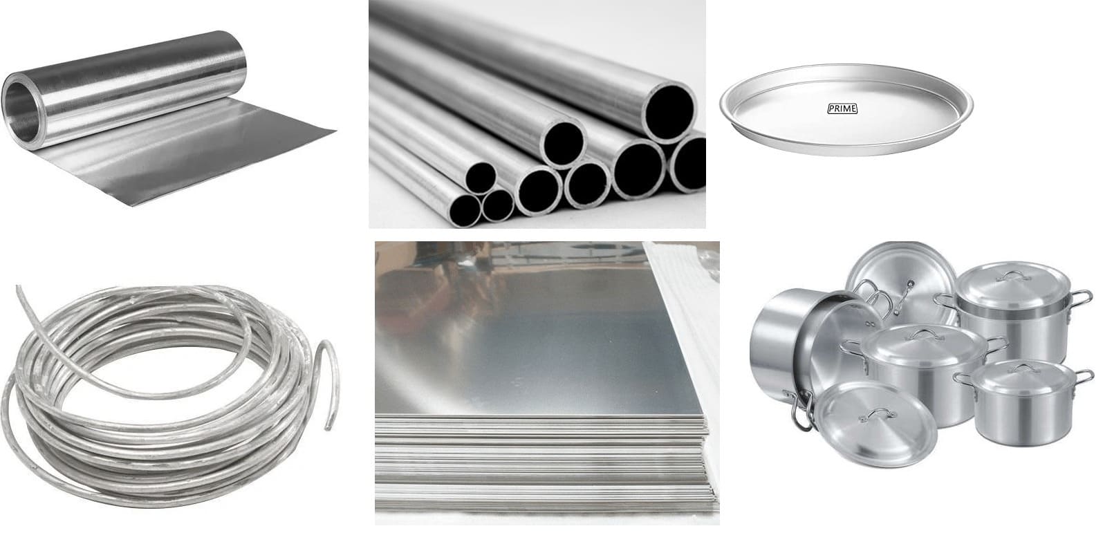
Material used for making Camshaft:
When it comes to the manufacturing of camshaft, there are mainly two materials are being used which are Iron and Steel. The Iron material is used for high volume production and Steel is used for low volume production and high-quality camshafts.
The camshaft is used for high rigidity, therefore cast iron material is used as it offers great strength. Some other materials are also being added to Iron before casting.
This is manufacture by the Forging or casting process and further, it is machined by a Lathe machine.
Reason for Failure of Camshaft:
It is a very important part of an engine. When it gets damaged, it can create failure of an engine. Let see what may be a possible cause for the failure of the camshaft:
- Damage of cam of the Camshaft.
- Incorrect valve spring pressure.
- Improper break-in.
- The problem with the lob wear because of not proper lubricant. and so on.
Difference between Camshaft and Crankshaft:
| Camshaft | Crankshaft |
| It is used for closing and opening of engine valve for the right timing. | The crankshaft is used to convert the reciprocating or oscillation motion of the piston into the rotary motion. |
| It is attached to a crankshaft and rotated by a timing belt. | The crankshaft is being rotated with the help of a Piston. |
| This is located at the top of the cylinder head. | It is located bottom of the cylinder head. |
| It can be made with two metals Iron or steel. | Crankshafts are made with alloy steel. |
Advantages of camshaft:
The following advantages are:
- Camshaft enables proper inflow and outflow of fuel and exhaust gases respectively.
- The design is quite simple.
- It is durable and easy to maintain.
- Provides smooth operation even at high speed.
- A single camshaft can be used for many cylinders.
Disadvantages of camshaft:
The following disadvantages are:
- Overheating problems are usual with camshafts.
- A broken camshaft may cause serious damage to the engine.
- The cost of it is costly.
Applications of camshaft:
The main application of camshaft is in internal combustion engines. Camshafts with gears were also used to operate oil pumps. It is also used wherever there is a need to convert Rotary motion to linear motion.
Related Resources:
- Propeller Shaft
- Braking System Types
- Single Plate Clutch
- Multi-Plate Clutch
- Clutch complete Notes
- Electronic Ignition System
- Battery Ignition System
- Magneto Ignition System
- Lubrication System Types
Reference:
- An overview by Energy Education
- Working and Drive system by Wikipedia
- Youtube Video: Selva Kumar
Conclusion:
So here we have studied in detail. Let me know what else I can help you in this topic or any other topic?. You can check our another article I am sure that can boost your knowledge. Till then Thank you for reading.


Discussion about this post