Hello, Hope you are well. Today we are going to read Synchromesh Gearbox in detail. Starting with History, then Definition later on working principle, advantages, disadvantages, and application in detail.
Note: The PDF of this article you can easily download at the end of the articles.
Since the introduction of the constant mesh transmission system, various inventors have tried different types of modifications to overcome the limitations caused by it. The problem was that the constant-mesh gearbox provided a rough and noisy transmission system.
Moreover, the dog clutches used in the constant mesh system were in direct mesh with the rotating gears which causes a harsh shifting of gears.
It also showed signs of wear and tear which increased the maintenance of the system.
The synchromesh gearbox was invented by Earl Avery Thompson, in the year 1919. He was an engineer who majored in mechanical and electrical engineering. Thompson’s synchromesh transmission design was first used in Cadillac and LaSalle cars in the year 1928.
He sold his synchromesh transmission patents to General Motors in 1924 and 1930 for a reported fee of around $1 million.
But most cars continued to use the non-synchronous transmission system until the 1950s.
In 1947, Porsche started using the split ring synchromesh system, which went on to become the most common design.
The Porsche 356 in 1952 was the first car to use the synchromesh system on all forward gears.
What is a Synchromesh Gearbox?
The synchromesh gearbox is a type of manual transmission system in which transmission changes occur between gears rotating at the same speed. In this type of gearbox, the gears on the layshaft are fixed to it and the gears on the main shaft can either roll freely when disengaged or be locked on the layout shaft when engaged.
It is an upgrade on the dog clutch and constant mesh gearbox which were invented earlier.
The difference is that of synchronizing technology used to avoid the clattering or grinding noise during changing of gears due to the difference in speeds of the input shaft and output shaft.
It avoids the need for declutching from the driver. This is based on special shifting devices called synchronizer rings which are used to bring the parts to be engaged into frictional contact which equalizes the speed after which these may be engaged smoothly.
It usually consists of a 5 or 6-speed 1-reverse manual transmission configuration. It is also used in racing cars due to its quick and smooth response.
Now we will see parts and their function of Synchromesh Gearbox in detail.
Construction or Parts of Synchromesh Gearbox:
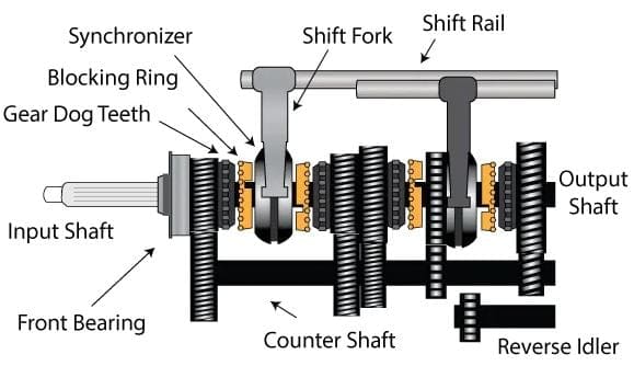
The components involved in the synchromesh gearbox are parts such as clutch shaft, layshaft, main shaft, needle bearing, synchronizer, helical gears, spur gears, idler gear, shift fork, and shift rod.
We will study one by one in detail.
#1. Clutch shaft:
A Clutch shaft is used as an input shaft as it is used to carry the engine power output to the gearbox. It is also called the input shaft. The input gear is mounted on the clutch shaft.
#2. Layshaft:
Layshaft is used as an intermediate shaft over which suitable gears are mounted and is used to transmit the motion from the clutch shaft to the output shaft.
It is also called a countershaft. Gears of different sizes suitable to the corresponding main gear are mounted on the layshaft. It is used in the transfer of power from the clutch shaft to the main shaft.
#3. Main shaft:
It is the shaft that is used to transmit the torque/power generated in the gearbox to the differential of the vehicle. It’s also called the output shaft.
The needle bearing and splined section are mounted on the main shaft. It rotates independent of the gear and the gear only rotates when it’s engaging to the shaft with the help of the synchronizer.
#4. Needle bearing:
It is mounted on the main shaft and the gear is locked onto the teeth of the bearing. It is used to lock the gear and main shaft so that the main shaft rotates along with the gears.
Along with the needle bearing are the splined sections mounted on the main shaft parallel to the needle bearing. The synchronizer hub is fitted over the splined sections.
The splines lock the synchronizer hub so that it also rotates along with the gear when engaged.
#5. Synchronizer:
The synchronizer ring consists of three parts, namely synchronizer hub, synchronizer sleeve, and synchronizer blocker ring.
The synchronizer hub is the inner ring mounted over the splined section and the synchronizer sleeve is the outer ring. The outer surface of the hub and the inner surface of the sleeve are both splined, which interlocks the two parts.
The sleeve can move horizontally on the splines of the hub. When the main shaft rotates, the synchronizer system rotates along with it.
Synchronizer blocker ring is the outermost part fitted at both ends in the synchronizer system; it has straight teeth at the edges. It rotates along with the sleeve and the hub.
When a gear is selected, the blocker ring rubs with the gear. It is used to lock with the straight teeth/ spur gear present at the outer edge of the gear. The locking action increases the friction between the gear and the sleeve, which is used to sync or match the speed of the gear and sleeve before the gear is engaged.
This causes the gear and sleeve to rotate together reducing clattering of the rotating parts and making a smooth transition.
The synchronizer is placed between pair of gears and the shift fork is connected to it. When a gear is engaged or disengaged, the shift fork moves the synchronizer back and forth.
#6. Helical gears:
Helical gears namely, input gear, counter gear, and output gear are mounted on the input shaft, layshaft, and the main shaft respectively. These gears are preferred since the gear teeth are at a certain angle called the helical cut.
The gear teeth gradually engage multiple teeth from one side to the other.
This distributes the stress on the gears and makes the gears mesh much quieter than the straight cut spur gear. The input, counter and output gears are always in constant mesh and rotate together.
NOTE: The main or output shaft does not rotate with the gears in constant mesh until the gear is engaged.
#7. Spur gears:
The spur gears are used on the edge of the helical gears and rotate along with it. It is also called dog’s teeth.
The straight cut teeth present in it are used to lock on to the synchronizer blocker ring which ultimately locks the sleeve and allows it to rotate at the same speed as the gear after syncing the speed.
The idler gear used to reverse the output shaft is also a spur gear.
#8. Idler gear:
The idler gear is used to reverse the direction of the output shaft. When engaged, it is placed between the counter gear and output gear. This makes the output gear rotate in the opposite direction.
#9. Shift fork:
Shift forks are connected to the synchronizers between gears. Each shift fork and synchronizer is used to engage or disengage a pair of gears.
It moves the synchronizer back and forth between the gears. It is linked to the shift rod, which moves the shift fork when a driver uses the gear shifter.
#10. Shift rod:
The shift rod is connected to the shift fork at one end and the gear shifter at the other. It is used to transfer the force exerted by the driver on the gear lever to the gears via the shift forks.
Synchromesh Gearbox Working principle:
Transmissions work on the principle of providing torque and speed as required. Low gears provide low speeds but high torque, whereas high gears provide high speed but low torque.
Torque in an automobile is the force at which the shafts rotate. Another important point to note is the gear ratio, which is given by the ratio driven gear: driver gear.
The gear ratio decides the speed at which the meshed gears can produce. For example, if both the gears are of the same size the gear ratio is 1:1.
But if the driven gear is double the size of driver gear, it provides a ratio of 2:1.
In the case of an automobile gearbox, the driver gear is the input gear linked with the clutch shaft and the driven gear is the output gear linked with the output or main shaft.
The counter gears are present just to link the driver and driven gear due to the different sizes of gears present.
This is how gears bigger in size with respect to the input gear are used to increase the speed and lower the torque of the vehicle.
The principle of a synchromesh gearbox is that “the gear and synchronizer are fractioned with each other earlier than the gear are engaged and engagement is done when the speed is matched”.
Working Step by Step of Synchromesh Gearbox:
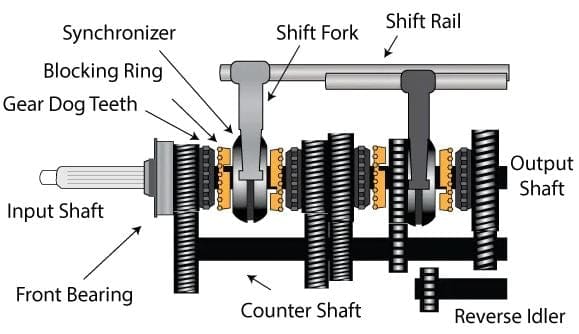
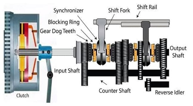
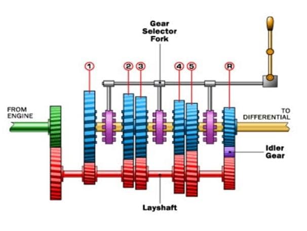
As shown in the figure, a synchronizer is present between a pair of gears. In most cases, the pairs are first-second, third-fourth, and fifth-reverse. The location of the reverse gear may differ according to the manufacturer’s design.
The gears on the clutch shaft, layshaft, and main shaft rotate along as long the clutch shaft rotates due to the power provided when the engine. When the driver needs to engage the first gear, the clutch is disengaged which brings the rotating parts to a complete stop.
The gear shifter is then pushed to the first gear, which pushes the shift rod. The shift rod makes the fork move the synchronizer towards the first gear.
The blocker ring rubs against the dog’s teeth or straight cut teeth to lock on to the gear and sync the speed.
When the driver engages the clutch again, the blocker ring causes the synchronizer sleeve to rotate along with it and the speed of the rotating parts are matched.
When the speed is matched the synchronizer sleeve moves the gear across to interlock it with the output shaft.
For the second gear, the driver disengages the clutch and uses the gear shifter to disengage the first gear and move the shifter to the second gear.
This causes the fork to move the synchronizer from first gear to second gear. The blocker ring and sleeve are pushed which synchronizes the speed and interlocks the second gear.
The third and fourth gear works on the same principle. The only difference is that the pair of gears are engaged using a different shift fork and shift rod.
The fifth gear is engaged when the driver disengages the clutch and moves the shifter from the fourth to the fifth gear. The fork moves the synchronizer from fourth to fifth gear.
The blocker ring and sleeve are pushed which synchronizes the speed and interlocks the fifth gear.
For the reverse gear, the vehicle is brought to a complete stop and the clutch is disengaged. Then the driver moves the shifter to reverse, which causes the idler spur gear to slide in between the first gear and counter gear.
When the clutch is re-engaged, the direction of the output shaft is reversed. So, this is how an engine is used to propel a car, and gears are used to move the car faster.
Advantages of Synchromesh Gearbox:
Some of the advantages of Synchromesh Gearbox are following:
- De-clutching is not required as in case of the constant mesh gearbox.
- Helical gears present make lesser noise compared to other gears due to teeths cut at a certain angle.
- Synchronizer device present avails quiet transition of gears in synchromesh gearbox.
- There is no loss of torque during the transmission due to the synchronizers.
- As a result, it can provide more power transmission.
- Vibration of the gearbox is less.
- The clattering and grinding problem of constant mesh gearbox can be overcome using synchromesh gearbox.
Disadvantages of Synchromesh Gearbox:
Some of the disadvantages of Synchromesh Gearbox are following:
- The synchromesh gearbox is costly due to the manufacturing cost of the fine and small parts present in the system.
- It is a more complex and bulky system, as a result servicing becomes difficult.
- Greater amount of space is required.
- Improper engagement of gears can lead to damage.
- Higher loads can cause the teeth coming in contact to break, hence it cannot handle too high loads.
- Some cars use a synchronizer system only on the higher gears and use constant mesh gears on lower and reverse gear. This is done to decrease the manufacturing cost.
Synchromesh Gearbox Application:
Most modern cars use a synchromesh gearbox. It is also used in racing cars with some modifications in the gearbox as they require the shifting of gears at high torque and speed.
Internal Resources:
- Gearbox Complete Notes
- Clutch complete Notes
- Different Types of Clutch
- Different Types of Brake
- Lubrication System Types
- Magneto Ignition System
- Battery Ignition System
- Single Plate Clutch
- Multi-Plate Clutch
- Drum Brake vs Disc Brake
- Battery Ignition System
- Magneto Ignition System
- Electronic Ignition System
- Flywheel
- Camshaft
- Crankshaft
Reference [External Links]:
- Youtube video: https://youtu.be/vOo3TLgL0kM
- https://www.slideshare.net/ParthDasadiyaGnvantb/synchromesh-gear-box-84565294
- https://www.carthrottle.com/post/how-does-a-synchromesh-work/
- https://irejournals.com/formatedpaper/1701015.pdf
So here we finally studied all the Synchromesh Gearbox in detail. I hope you have understood this topic. If yes then please share it with your friends and family. Do let me know what further topic I can help you with. Till then Thank you so much for visiting. Bye

![Steel: Properties, Different Types and Applications [Notes & PDF] Feature Image of Steel](https://themechanicalengineering.com/wp-content/uploads/2023/01/Feature-Image-of-Steel-300x168.jpg)

Discussion about this post