Today In this article we will get to know about the cylinder head in detail which is an important part of the Internal Combustion Engine.
It plays a vital role in the engine and has a complex design. The design of the head requires lots of mathematical equations & calculations and precision machining to get the desired results.
Before moving to our main topic in detail first we should know the cylinder of the IC Engine.
What is Cylinder?
The function of the cylinder in IC engines is to hold the fuel and guide the piston. The cylinders are made of mainly Cast iron and Cast steel. There is fuel combustion inside the engine cylinder that takes place and it keeps the temperature of the engine cylinder very high. Therefore It is necessary to provide cooling in the engine cylinder.
Cylinder Head Definition:
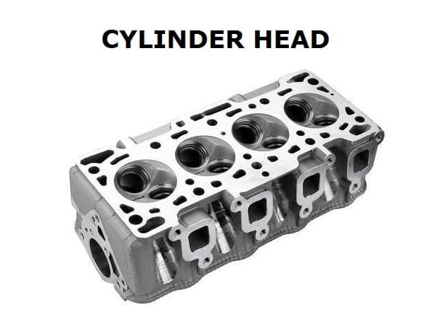
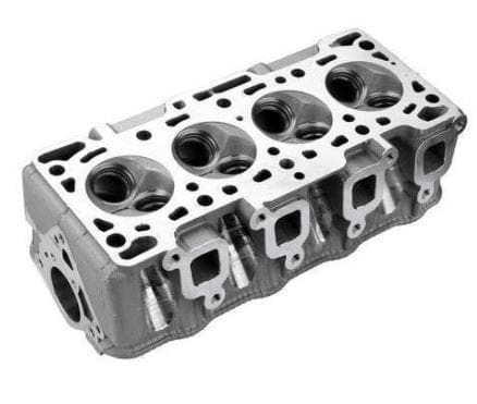
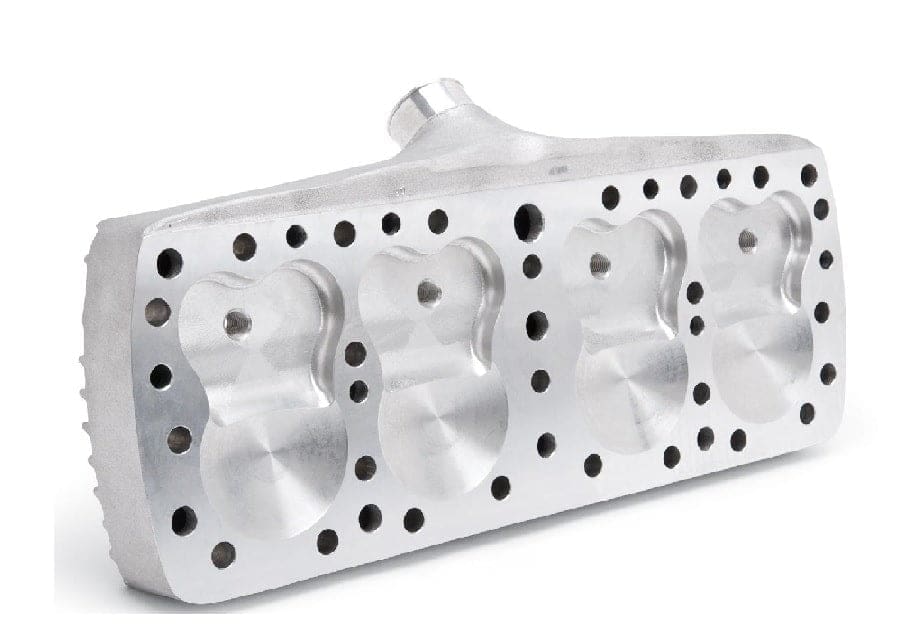
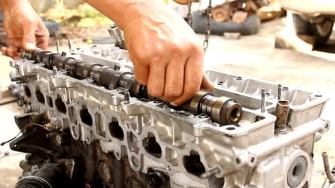
The cylinder head is the top cover of the engine cylinder and It seals the top of the cylinder. Internal combustion engine cylinders are covered with help from the cylinder head. It is above the cylinder block. And this is fitted with a camshaft and all kinds of valves.
- The cylinder head consists of grooves for spark plugs and exhaust gas for the passage of air fuel, and for fuel injection in the case of diesel engines.
- The cylinder and head are attached to the bolt’s help.
- Between the cylinders and the cylinder heads, asbestos packing and metal gasket are provided which help the joints to become leakproof.
- The material used for making cylinder heads is cast iron or Aluminium alloy [Aliminium Alloy is preferred as first priority because of its lightweight and high thermal conductivity].
Cylinder Head Parts or Construction:
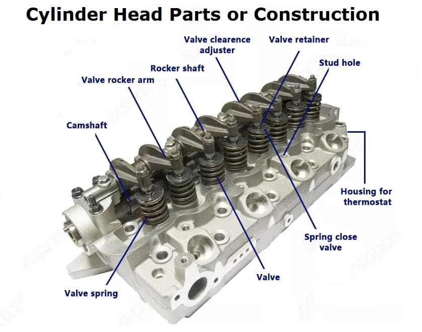
Now, let’s discuss how the cylinder head is built. There are many types of holes in it, So what is the work of those holes and where are they used, Let’s discuss it.
The cylinder head contains a variety of holes to connect the cylinder block to the cylinder head, Some of the holes are made for water jackets for proper water circulation to provide cooling and lubrication.
While cylinder head contains some critical engine parts provided for the seat of valves such as the inlet valve, exhaust valve, valve guides, injectors, spark plug, etc.
In the SI engine, the combustion chamber is also provided in the cylinder head. There is also an arrangement for a heater plug and for injection in the cylinder head.
A thermostat valve is installed at its outlet elbow for the circulation of water which is connected to the radiator.
The cylinder head itself consists of a combustion chamber where petrol or diesel is combusted through a variety of intake and outlet manifold valves.
It also has holes for providing oil at every stage in the cylinder.
- Cylinder Block
- Cylinder Head Gasket
- Piston
- Camshaft
- Valves
- Valve Spring
- Spark plugs
- Injector
- Intake Manifold
Now we will study them one by one in detail, Start with the cylinder block,
Cylinder Block:
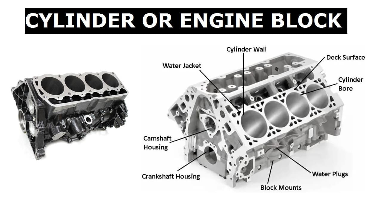
The cylinder is the part that supports the structure of the engine cylinders and their related parts. It is the lower part of the engine cylinder.
Cylinder Head Gasket:
It is set up or mounted between the engine block and cylinder head, It established the seal between the two components.
The cylinder head gasket provides the functions of coolant in applicable passageways. It is used to prevent air and combustion gas leakage, and to keep the compression of the engine cylinder.
Piston:
It is a disc that reciprocates inside the cylinder at the time of the combustion process of the engine.
Its main work is to transfer the energy by acquiring the impulse which is being generated from the gas inside the cylinder and transferring the energy from the connecting rod to the crankshaft.
Camshaft:
It has the function to push the valve open in the cylinder head. Camshaft means a shaft that has a cam along with the shaft. The camshaft presses the valve with proper timing so it is made in established conditions so the crankshaft rotates. A camshaft helps an engine to work well.
Valves:
It is also called a door between the combustion chamber and outside air.
It acts as a gate because the function of the valve is as a place of exit material. Generally, two valves are used on a 4-stroke engine, to handle suction and exhaust.
Valve Spring:
It has a function to hold the valve position concerning to close tightly. A valve spring is used to regain the manifold position after being pressed. It is pointed in a down position with the spring.
Spark plugs:
A spark plug fire the electricity inside the combustion chamber, with the help of a spark plug engine, and runs efficiently because of the position of the spark plug at the top point that’s why the resultant energy pushes the piston directly.
So, the engine can work more efficiently. so the spark plug is located in the cylinder head, not on the cylinder block.
Injector:
For different types of engines, different ignition methods are employed. In diesel engines, the injector directly leads to the combustion chamber so it does not need spark plugs.
Intake Manifold:
In this intake manifold air comes from the air induction system which is a tubular part.
The intake manifold is varied and for bubble design, there are also some standards. Bubble design prefers to make the air be more leveraged in the air intake process.
Cylinder Head Function:
The main function is:
- Cylinder Block with a piston inside has done four actions i.e. suction, compression, power stroke, and exhaust.
- Suction and exhaust have been performed without the cylinder head but for compression and power stroke, a cylinder head is necessary.
- So Power stroke will not be available until it is compressed So we use the cylinder head to cover the cylinder block for proper compression and power stroke.
- Its structure is molded by looking at the two-stroke, four-stroke, and six-stroke according to the requirement.
Cylinder Head Types:
The cylinder head has been classified into various factors. It also depends on the arrangement of ports and valves.
- Loop flow types
- Offset cross-flow types
- In-line cross-flow types
- Water-cooled Engine
- Air-cooled Engine
- Flathead cylinder head
- Overhead-valve cylinder head
- Overhead camshaft cylinder head
Now we will study one by one.
Loop Flow Types:
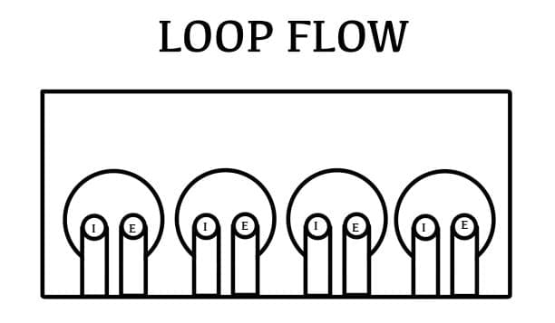
A loop flow type cylinder head is a type of cylinder that has the intake and exhaust ports on the same side of the engine.
The gases are brought into the cylinder head and then change their direction while exiting the head. This is the opposite in working with the crossflow cylinder head system.
The advantage of the loop flow type is that both the entering inlet charge and the exiting exhaust gas cause a tendency to swirl in the same direction in the combustion chamber, which helps with the preheating of the intake air.
This produces a constant flow during the overlap, which promotes better mixing and scavenging of the end gas.
The disadvantage of the loop flow type is that there is limited space on one side of the head when inlet and exhaust ports are arranged in a line, causing a reduction in the port area as compared to a crossflow head.
It affects power delivery at high rpm due to the limited airflow.
Moreover, since inlet and exhaust manifolds are both on the same side of the engine and in close proximity to each other, the inlet manifold and carburetor (if applicable) are heated due to the exhaust.
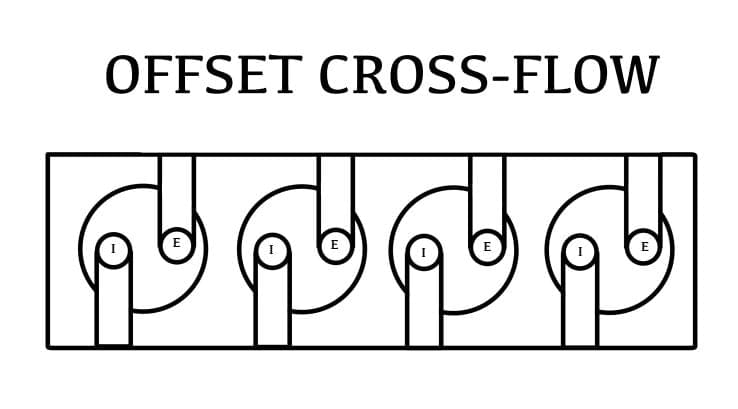
Offset Cross flow types:
A crossflow cylinder head is the one that features the intake and exhaust ports located on the opposite sides.
The gases are introduced to flow across the head. This is the opposite of the loop flow type cylinder head design that has the ports on the same side.
Cross flow types use an overhead valve, but also can be actuated by overhead camshafts, or either by a valve-train, which contains the camshafts in the cylinder block and the valves are actuated with pushrods and rockers.
Cross Flow type provides better performance and efficiency than the loop flow type cylinder head.
The explanation for this is that the gases don’t have to change direction and hence are moved into and out of the cylinder more efficiently, is a simplified process as there is no continuous flow because of valve opening and closing.
But there is a point between intake and exhaust in which both the valves are open due to overlap.
The inertia of the exhaust gases leaving the cylinder at that point helps to aspirate intake gases into the cylinder.
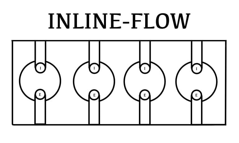
In-line cross-flow types:
The inline cross-flow type cylinder head is similar to the offset cross-flow type.
The major difference here is that the valves are arranged in such a manner that they are transversely and inclined to each other.
But, the inlet and exhaust port are positioned opposite each other, on the different sides of the cylinder head.
This arrangement is better in terms of performance and efficiency but the cost of manufacturing is high as a result it is not feasible.
On the basis of cooling requirement, it is of two types:
- Water-cooled engine
- Air-cooled engine
Water-cooled Engine:
Different types of water jackets are used in the head of the water cooling engine for the circulation of water.
The water-cooled engine system uses a pressurized and closed system. The pressurized system involved increases the boiling point of the water to above the 110 °C points.
As a result, the water evaporation rate slows and could be used for a prolonged time. The circulating water dissipates the heat from hot engine parts such as the cylinder head and the cylinder block.
A cooling fan is used to cool the water when it passes through the radiator. An IC engine is cooled by either liquid or water, known as a liquid or water-cooled engine.
Most modern high bikes, cars, and other vehicles use liquid or water-cooled engines.
A liquid-cooled engine is very similar to a water-cooled engine and the only minor difference is that the liquid-cooled engine uses water as its main component but it is a mixture of concentrated coolant and water with a 1:1 proportion.
Air-cooled Engine:
Here Fins are used in air-cooled engines for maximum cooling. It is made of aluminum alloy And is Light in weight.
An air-cooled engine relies on the circulation of air directly over the hot areas of the engine to cool them so that the temperature of the engine is within the operating conditions.
Most of the heat generated escapes through the exhaust and some escapes through the metal fins of the air-cooled engine. These engines have some fins extending out to pull heat away from the engine.
A fan is then used to force cool air over the fins. The heat generated is directly released into the air by an air-cooled engine. This is in contrast to the liquid or water-cooled engine which has a closed circuit coolant-carrying system.
The air used for the cooling purpose is forced above or onto the hot area. This air is generated either using a fan or by natural air flow with well-designed and angled fins.
Air-cooled engines provide simplicity in terms of design and maintenance but usually runs with a loud noise which is quite a disadvantage.
On the basis of the function of the cylinder head it is of three types:
Flat-head cylinder head:
It has no flexible moving parts it only comes up with protection for the cylinder block and the performance of the engine of this head is very poor because of the inefficient flow of air.
This type of cylinder head consists of a singular component of cast iron metal without the presence of any mechanical parts. Apart from the simple structure, the flathead cylinder head type has its drawbacks.
These are also known as side-valve engines or valve-in-block engines. It is basically an internal combustion engine with the poppet valves contained within the engine block, instead of in the cylinder head, which is in the case of an overhead valve engine.
Their valves are located on the sides of the engine block. This leads to the intake gases moving at an angle of 90°, leading to inefficient combustion and a lower compression rate.
Due to its flaws in the design, the flathead cylinder is no longer used much in the industry. It is easy to manufacture and requires less capital, the head allows the coolant to flow effectively.
It is lightweight and also allows for a compact engine.
Flathead cylinder heads were used by automobile companies worldwide from the 1890s till the 1950s but then got replaced by the more efficient overhead valve and overhead camshaft engines.
It is usually used in smaller engines such as those used in lawnmowers, small tractors, and agricultural vehicles.
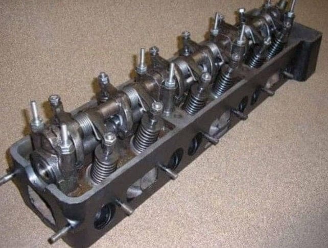
Overhead-valve cylinder head:
It is good compared to the flat-head cylinder. Airflow is very much easy and efficient as compared to a flathead cylinder, and the camshaft is situated above the pushrods.
The overhead-valve cylinder head is complex in construction and it is also known as the I-type cylinder head.
It is a piston engine in which the valves are positioned in the cylinder head above the combustion chamber.
This is opposite to the flathead engines, where the valves were positioned below the combustion chamber in the engine block.
It consists of the valve parts, sparks plugs, and passageways for intake and exhaust gases. Engines with overhead-valve cylinder head types tend to perform better than others due to the location of the valves and intake passages.
The flow of intake gases is fast and smooth in this system due to the better design of the paths.
The advantage of using this type of cylinder is that the exhaust ports are also more efficient and the head does not get overheated when compared to the flathead type.
It also has the camshaft located closer to the crankshaft.
Overhead camshaft cylinder head:
This is situated right inside the head means here pushrod is not required. It contains a very advance the structure of cylinder head. It makes the engine very smooth because the flow of air is very smooth in this design.
This is a piston engine where the camshaft is positioned in the cylinder head above the combustion chamber. This is different from the earlier overhead valve engines, where the camshaft is positioned below the combustion chamber in the engine block.
This type of cylinder head has a valve train, spark plugs, and intake and exhaust ports, along with the head housing the camshaft. The location of the camshafts within the cylinder head varies in this.
It can be positioned in the middle, in the middle of a row of valves, or at the top of the valve. An overhead camshaft cylinder head is available with two configurations namely single overhead camshaft and a dual camshaft.
In a single overhead camshaft cylinder head, the intake and exhaust valves are in a single camshaft. In a dual overhead camshaft cylinder head, there are two separate camshafts for the intake valve and exhaust valve.
Single overhead camshafts have one camshaft per bank of cylinders and dual overhead camshaft engines have two camshafts per bank.
Dual overhead camshafts are also known as twin cams. The first car to use a DOHC engine was produced in 1910.
The use of these engines slowly increased from the 1940s, leading to most automobiles by the early 2000s using these types of engines.
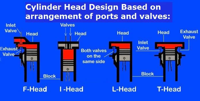
Classification based on an arrangement of ports and valves:
According to the arrangement of the inlet valve and exhaust valve in the cylinder head or block of an engine, automobile engines are classified into four categories.
These arrangements are namely, ‘L’, ‘I’, ‘F’, and ‘T’ head.
An easy method to recollect this topic is to remember the word ‘LIFT’ to recall the four-valve arrangement.
F-Head engine:
The F-Head engine is a combination of I-head and L-head engines. In this type of engine, the inlet valve usually is in the head and the exhaust valve lies in the cylinder block. Both the valves are operated using a single camshaft.
I-Head engine:
In the I-head type of engine, the inlet and exhaust valves are located in the same cylinder head. A single valve is used to actuate all the valves. These types of engines are commonly seen and used in automobiles.
L-Head engine:
In these types of engines, the inlet and exhaust valves are arranged in such a way that the valves are side by side with each other and are operated using a single camshaft. The cylinder and combustion chamber forms the shape of an inverted L.
T-Head engine:
In T-head type of engines, the inlet valve and the exhaust valve are located on either side of the cylinder. This system uses two camshafts that are required to operate. One camshaft is for operating the inlet valve and the other one is for operating the exhaust valve.
Cylinder Head Advantages:
- It is easier to produce from the manufacturing point of view.
- By changing the thickness of the gasket, we can change the compression ratio moderately.
- Maintaining operations such as decarbonizing and valve grinding are easy to achieve.
Cylinder Head Disadvantages and remedies:
Carbon freezing in the cylinder head, and there are two main reasons for this, one is the arrival and running of oil in the combustion chamber and the second reason is not to run the fuel properly means overall Uncontrolled combustion in cylinder head due to which fuel will not burn completely and will generate carbon. and it sits on the carbon cylinder head and will jam the other parts. So to avoid carbon freezing, De-carburising is a method through which we can open the cylinder head and clean the carbon from it through a scraper.
It has a problem of scale formation in water jacket due to hard water Due to which the flow of water takes place but there is no exchange of heat transfer, Due to which the engine runs very hot. To solve this problem, soda is poured into the radiator and It is stirred for a while in the engine Then clean it down with the help of the reverse facing method which removes the crust.
Another problem is that if we put cold water in the hot engine, it gets cracked.
Cylinder Head Application:
The following application is:
- For Lubrication in an Internal combustion engine
- To provide a leakage-proof cylinder in an IC engine
- To ensure proper combustion in the IC engine cylinder
- To prevent the engine parts from any Defects
- To cover the cylinder head for proper compression.
Cylinder Head Material:
There are two main materials used here and that is:
Cast Iron: Cast iron is ferrous metal because it contains iron. To convert pure iron to cast iron we combine the mixture of carbon mainly (2-4%) of carbon, sulfur which is less than (0.1%), phosphorus (1-1.5%), magnese(0.75%), and silicon(2.5%), etc.
Aluminum Alloy: It is the chemical composition of where we are added other elements to pure aluminum to increase the strength and property of the material because the only aluminum is softer in nature so we use the combination of various elements which is mainly iron, silicon, magnesium, manganese, and zink, etc.
How Cylinder Head is Manufactured or Manufacturing process:
The cylinder head is made through the separated casting process. These are cast from molten metal. normally, LFC (lost-foam casting) is used by manufacturers for cylinder head casting.
The polystyrene foam method uses to produce the essential pattern. This is the easiest process to produce good results for complex castings. It has the benefit of dimensional accuracy and excellent finish, among other advantages.
According to the requirement of performance, strength, and other factors cylinder heads are made from iron or aluminum.
Internal Resources:
- Master Cylinder
- Cylinder Liner
- Automobile Classification
- Air Suspension System
- Flywheel Camshaft Crankshaft
- Clutch complete Notes
- Single Plate Clutch
- Multi-Plate Clutch
- Drum Brake vs Disc Brake
- Battery Ignition System
- Magneto Ignition System
- Electronic Ignition System
- Different Types of Clutch
- Lubrication System Types
- Magneto Ignition System
- Battery Ignition System


![Different Types of Measuring Tools and their Uses [Notes & PDF] Feature Image of Types of Measuring Tools](https://themechanicalengineering.com/wp-content/uploads/2023/01/Feature-Image-of-Types-of-Measuring-Tools-300x171.jpg)
![Steel: Properties, Different Types and Applications [Notes & PDF] Feature Image of Steel](https://themechanicalengineering.com/wp-content/uploads/2023/01/Feature-Image-of-Steel-300x168.jpg)

Discussion about this post