The inertia principle of the flywheel can be found in potter’s wheel and Neolithic spindles. Mechanical flywheels can be observed in 1038-1075 for the smooth running of simple machines, such as lifting water from a bore well.
American medievalist Lynn White believed that a German artesian Theophilus Presbyter used the flywheel in many of his artifacts.
After the industrial revolution, James Watt was the first to design a modern flywheel with a crank mechanism for a steam engine.
In this article, we will study Definition, Function, Construction, Working Principle, Material, Advantages, Application in detail. And at the end, you will be able to download PDF easily.
Let’s start with our topic.
What is the definition of a Flywheel?
A flywheel is a heavy circular disc-like structure that is connected to the output shaft of the engine. It sounds very common when we talk about automobiles. It is also considered to be a part of the clutch mechanism.
Flywheel enables an engine to run smoothly without any change in the rotational motion of the transmission system.
In other words, we can say that It is a heavy mechanical device that is used to store rotational energy and supply it to the transmission system when required, this promotes smooth running of the vehicles.
The inertia of the flywheel eliminates or minimizes the fluctuations in the speed of the transmission system.
Functions of flywheel:
Here I have listed some of the functions:
- A flywheel promotes the smooth running of the vehicle.
- It stores energy during the power stroke and releases it during other strokes.
- It also helps in charging the battery.
- Balances the crankshaft.
- It is very important for starting the engine from the rest condition.
Flywheel Construction or Parts:
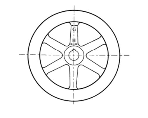
The flywheels are generally made by the casting process. This helps in maintaining the rigidity of the device. The structure of an armed flywheel is given below.
Rim:
The outer circular disc of the flywheel is called the rim. The rim is made heavier than the inner body this is to provide a better kinetic energy transfer.
The rim also has teeth on the outer surface with meshes with the electric motor and helps in the starting of the engine.
Once the engine is running it also generates electricity by rotating the motor and making it a generator.
Web or arms:
Web or arms are the supporting structure. It supports the rim against the vibrations caused due to the rotation.
The deciding factor of whether the flywheel should be an arm type or a web type depends on the size of the flywheel.
If the diameter is less than 600mm it is a web type and cast in one piece, if the diameter is greater than 600mm and less than 2.5m then it is arm type and cast in one piece and if the diameter is greater than 2.5m then it should be an arm type but here rim and body are cast separately.
Bore:
The bore of the flywheel is a hole made with a keyway to fit the driving shaft in it.
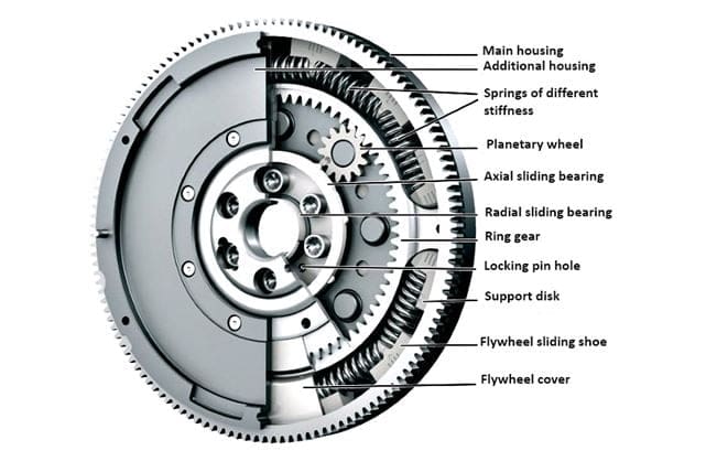
Structure of a Modern Flywheel:
- Cover
- Springs
- Planetary wheel
- Axial and radial bearings
- Support disc and
- Sliding shoe
The image shows the parts involved in a flywheel and their location:
Flywheel cover:
The cover is a structural casing of the flywheel it is rigid and solid. It also rotates and protects it against external barriers
Springs:
The spring used here acts as a damper for sudden vibrations. Hence, they protect from sudden jerks.
Planetary wheel:
A planetary wheel is situated with a planetary gear. When this gear is rotated and it provides a compound moment of other internal gears.
Axial and radial bearings:
Whenever there is an imbalance in the radial forces, these are compensated by these bearings.
Support disc:
A support disc is situated inside to support the springs and other moving parts.
Sliding shoe:
This is situated on the inner wall of the flywheel and is used to reduce the wear caused.
Now we will study it’s working,
How does Flywheel Works?
To understand the working we must first understand the working principle of the flywheel first.
The basic working principle of a flywheel is that it absorbs rotational energy during the power stroke and delivers that energy during other strokes ( suction, compression, and exhaust).
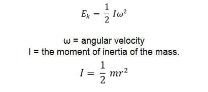
The energy equation depends on the angular velocity and moment of inertia of the flywheel.
Thus, it is obvious that the energy stored in a flywheel will increase with the increase in weight, size, and angular velocity.
Working method:
- The electric motor gives power to the flywheel at the very initial stage.
- This movement causes the piston to move and burn fuel inside the combustion chamber.
- Once the power stroke is activated the flywheel draws power from the power stroke and uses it for the other three strokes.
- In this way, It helps in stabilizing the rotational movement of the transmission system.
Different Types of flywheel:
There are 4 basic types:
- Solid Disc
- Rimmed
- High Velocity and
- Low velocity Flywheel.
Solid disc:
A solid disc flywheel is made of cast iron. It has a solid cross-section and provides better strength and stability.
Rimmed:
A rimmed flywheel will undergo wear under a lower rpm than the solid disc of the same dimension. It is ideal for low-capacity engines with high torque and low velocity.
High-velocity:
The range of a high-velocity is from 30000RPM to 80000RPM. They are lighter hence rotate at high velocity.
Low-velocity:
The range of a low-velocity is less than 10000RPM. They are comparatively heavy and hence rotate at low velocity.
Materials used for making Flywheel:
The materials used for making a flywheel are:
- Cast Iron
- Steel and
- GFRP
Let’s understand one by one in detail,
Cast iron:
Traditional flywheels are made of cast irons. The major advantage of cast iron is that it is cheap. There is minimum or no need for machining as it can directly be used after casting operation.
They also act as great dampers and absorb vibrations. They also have few disadvantages such as, they have sudden failure and they also offer poor tensile strength.
Steel:
Nowadays flywheels are made of high-strength steel as they offer better tensile strength and are corrosion resistant.
They are also very durable and do not undergo failure very easily. Steels are considered to be a better option when compared to cast iron.
GFRP:
GFRP stands for graphite fiber-reinforced polymer. This is considered to be the best choice for making flywheels for modern-day cars and automobiles.
They offer a great density and tensile strength and are perfect for making flywheels.
Advantages of flywheel:
- Smooth transmission of power with minimum fluctuations.
- High power output.
- An easy mechanism for smooth running.
- It also charges the battery via the motor.
- Cost-efficient.
- Low cost of maintenance.
- Not affected by high temperatures.
- It enables safe and reliable transmission.
- Has longer life hence it is durable.
Disadvantages of flywheel:
- Speeds are limited.
- Fatigue failure is possible.
- High chances of bearing failure.
- Cannot be controlled by the operator.
Applications of Flywheel:
- The most important application is in cars or any automobiles.
- It is also used in wind turbines.
- Many of the motor-driven generators use flywheels for storing energy.
- It is also used in satellites for direction control.
- Modern-day locomotive propulsion systems also use flywheels.
Internal Resources:
- Camshaft
- Propeller Shaft
- Clutch complete Notes
- Electronic Ignition System
- Battery Ignition System
- Lubrication System Types
- Braking System Types
- Magneto Ignition System
- Single Plate Clutch
- Multi-Plate Clutch
Reference [External Links]:
- https://www.explainthatstuff.com/flywheels.html
- https://en.wikipedia.org/wiki/Flywheel
- Youtube Video: Engineering Explained
Conclusion:
So here we have studied in detail. Let me know what else I can help you in this topic or any other topic?. You can check our another article I am sure that can boost your knowledge. Till then Thank you for reading.


![Steel: Properties, Different Types and Applications [Notes & PDF] Feature Image of Steel](https://themechanicalengineering.com/wp-content/uploads/2023/01/Feature-Image-of-Steel-300x168.jpg)

Discussion about this post