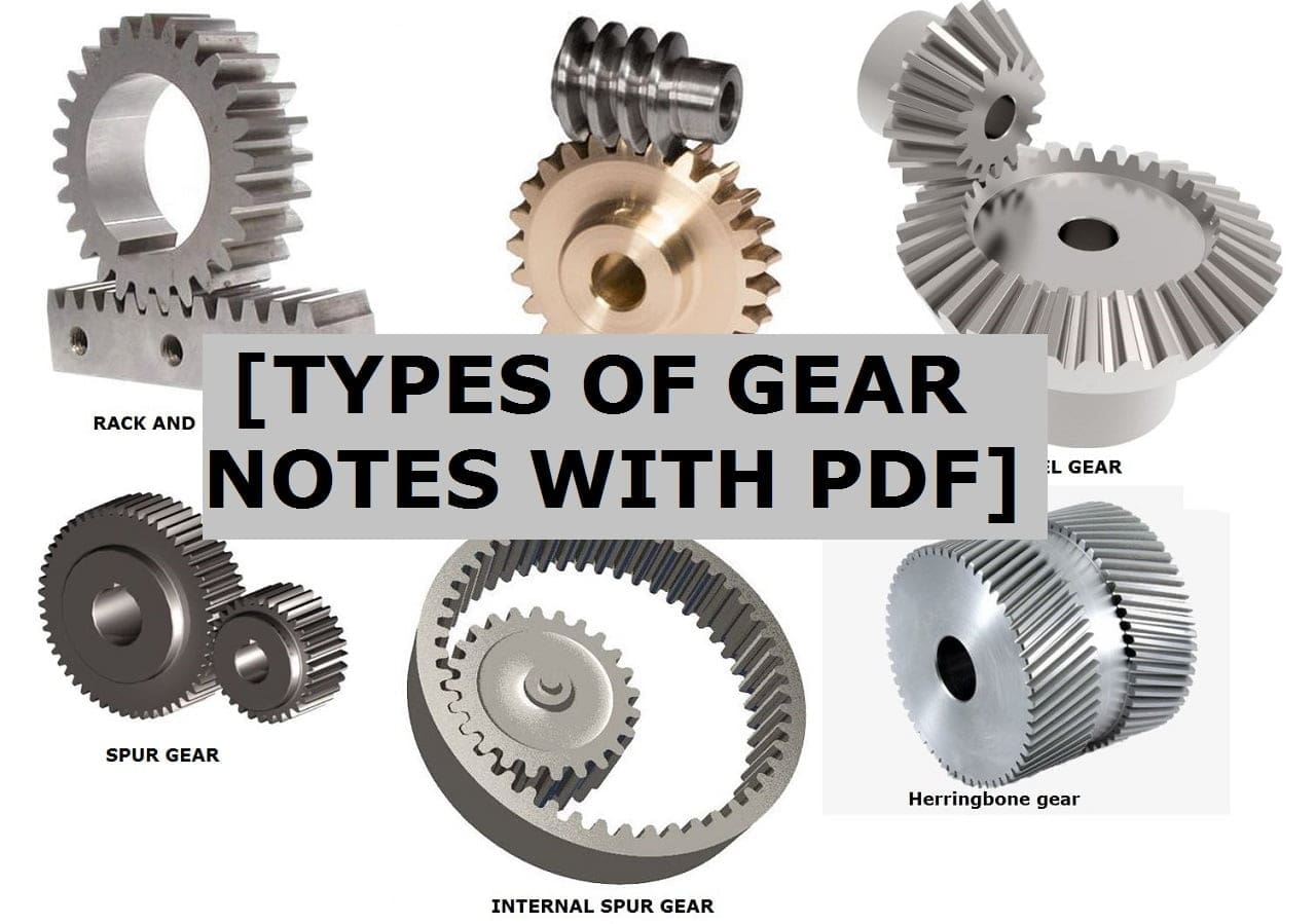
In this article, we will be study different types of gear and those are Spur Gear, Helical Gear, Double Helical and Herring Bone Gear, Crossed Helical Gears, and Worm Gear.
At the end of the article you can download PDF of this articles.
Gear is a Rotating Machine element that is having teeth which cut by the various Manufacturing process.
Gear Definition:
Gears are used to transmit power from one shaft to another. When teeth are Engaged, then power will be transmitted from the driver shaft to the driven shaft that has gears mounted on it.
The number of teeth will be different from the driver and driven By this factor we will obtain different speeds as required.
One important point gears do not Require Intermediate Link & Transmit motion by direct Contact.
Types of Gear:
The different types of Gears are:
- Spur Gear
- Helical Gear
- Double Helical and Herring Bone Gear
- Crossed Helical Gears
- Worm Gear
Spur Gear:
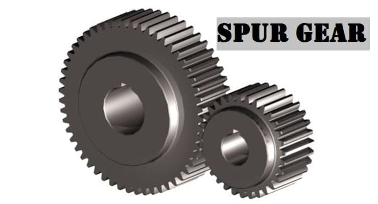
A spur gear is the most common type of gear. They have Straight teeth they are mounted on the parallel shaft. When the spur gears are Engaged the contact will be to the Entire width parallel to the Axis of the shaft.
Due to this these will the sudden application of load stress will be Impact & Detrimental (Dangerous) & Excessive sound when they are applied for high speeds.
So they are for moderate speeds. Gear can be Internal or external.
When the teeth are cut outside the cylinder, They are known as External gears and when teeth are cut inside, it is known as internal gears.
When External meshes, they will rotate in opposite directions, and when internal meshes they will Rotate in the same direction. As we know there is no axial thrust.
There is one Advantage of that bearing work will be Reduced. Due to the impact loading force is acting for very little time and Due to this, there will be chances of fatigue failure.
Spur Gear Application:
The following application of Spur gear is:
- Electric Screw Driver
- Washing Machine and
- Cloth dryer.
Helical Gear:
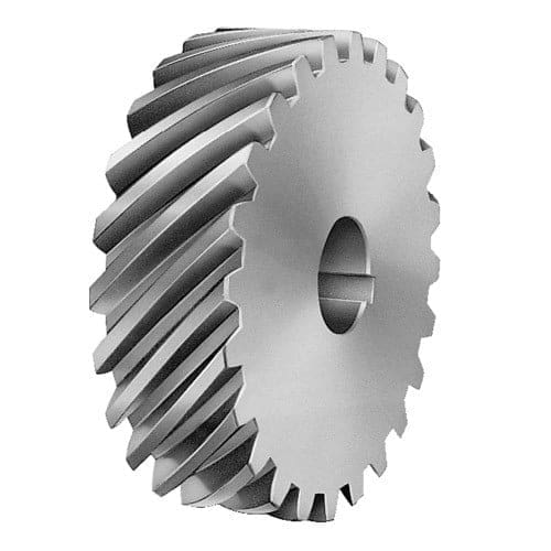
Teeth are cut at an angle so that when the teeth of helical gear Engage, the contact starts at one end of the teeth and It will gradually spread as the gear Rotate up to when the two teeth will be engaged fully.
So we can say :
- There will be a gradual Engagement.
- There will be less impact on teeth.
- There will be less noise.
- Due to the Angle of teeth, there will be thrust or Axial load that was not present in Spur gear So we have to use the bearing to minimize the load.
- These gears have higher load Carrying capacity & can be used for higher.
- The teeth can be Right-handed or left-handed. Right-hand teeth (when slope away from the viewer) and Left-hand teeth (when slope toward the viewer).
Helical Gear can be used in cars. The cost will be high.
The stresses will be normal stress that will produce bending in 2 planes Shear stress due to tangential force and Axial load due to teeth Inclination.
Helix angle: Angle at which teeth are Inclined to the Axis of gear. It is also called a spiral angle.
- Pn (Normal pitch): Shortest distance measured along the normal helix
- P (Pitch): It is the distance between two corresponding teeth.
Double Helical and Herring Bone Gear:
To overcome the Axial thrust in helical gears Double helical gears are used. These are like pair of helical gears secured together one will have a right-hand helix and the other will have a left-hand helix So the Effects of force will be equal & opposite and they will cancel out.
While joining the two helical gears a small gap is maintained between them. In Case of double helical gear sufficient gap is provided between the two Identical helical gears (The same module should be there) But the hand of the helix should be opposite It is easy to fabricate and cheaper.
Double helical gears are made by gear hopping process which is a highly productive gear making /gear cutting process. But due to the more Intermediate gap, it requires more space.
In the Case of herringbone gears, there is no such gap It is produced / Manufactured by the gear shaping process which is a slow process than the hobbing process.
Herringbone gears are mostly used in heavy machinery these gears have a side-to-side combination not face to face of helical gears because of no groove.
Bevel Gear:
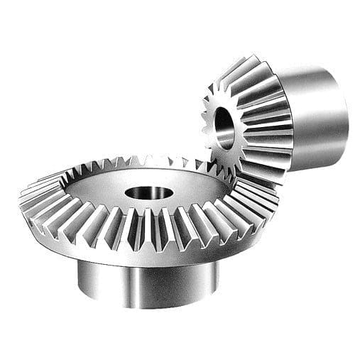
It can be assumed that the motion of the gears is two cones are rolling and there will be no slipping between them means the shafts will be intersecting type.
Simply when the teeth are made on the cone. It will become straight bevel gear and when the teeth are Inclined It is known as the helical bevel.
Bevel gears are mostly mounted for a shaft having a 90°angle between them but can be designed when the shafts will be at an angle. Note one thing the pitch curve formed of bevel gear is a cone .
Pitch surface is that can be Imagined when the gear meshes from peaks/crust and valley /root of Individual teeth .so pitch angle is angle between this pitch surface & the Axis of shaft for spur gear helical gear this angle was 90° But for bevel gear it is less than 90°.
This gear is useful when shafts are operating at angle means when power is transmitted at an operating angle .Bevel gears are used in differential drives. It is also used in mechanism of hand drill.
Crossed Helical Gears:
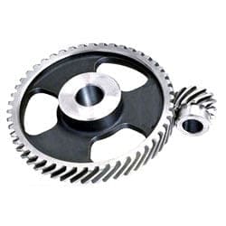
They are used for non-parallel, Non-intersecting shaft where uniform rotation or rotary motion is not possible. By just pure rolling here there will be some sliding motion too.
Hyperboloid: It is the surface of revolution generated by the skew line revolving around an Axis in another plane keep the angle between them as constant). The minimum distance between this skew line & Axis is called the throat of the hyperboloid.
So hyperboloid /generating surface will mesh & these can on a common line. Means line is common between the 2 gears.
But as we know that this is a case of different planes & mating hyperboloid have limited width & have the rolling motion for desired motion. Along the common line that two hyperboloids touch each other continuously, there should be rolling and sliding.
Crossed helical gears or spiral gears are limited to light load application will be machine tools, camshaft smell IC engine, etc.
Worm Gear:
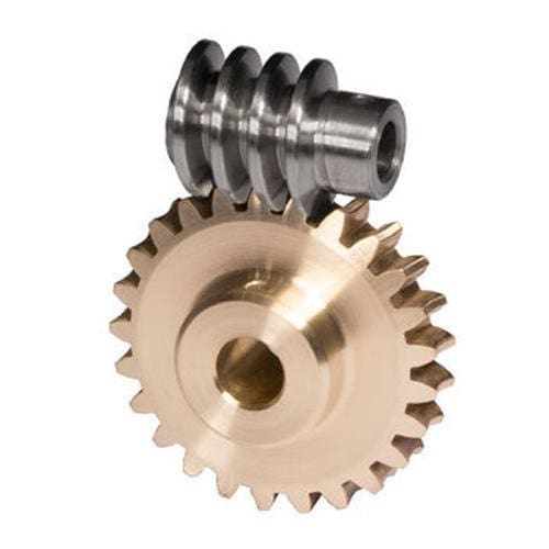
They come as worm and worm wheel worm acts as a driver. It has a very high spiral angle and Driven will be a worm wheel. We cannot make a worm wheel driver it will increase the normal reaction which will increase the friction.
Worm gears are used when large gear reductions are required. It is quite common up to 20:1-300:1.
It has a special feature due to the spiral angle that worm can easily turn the wheel but the wheel cannot turn the worm because friction will come into the picture . These gears are also non-parallel Non-intersecting shaft.
The shaft may have any angle but usually, they have 90°. The worm can be Imagined as a screw with a V thread & worm wheel as a spur gear.
The worm can be a single thread or multiple threads the concept is worm wheel with 24 teeth will provide year reduction of 24:1 & multi-start worm, the Gear reduction equals to No. of teeth divided by no. of starts on worm.
Secondly, It will provide high torques. They can also be used for speed reduction.
So here we studied all different types of gear.

Discussion about this post