Spur Gear is one of the important types of gear. Today we will study the Definition, Types, Terminology, Advantages, Disadvantages, and Application of Spur Gear.
At the end of the article you can easily download whole document in PDF format.
Spur Gear Definition:
Spur Gear is the most used gears, having Straight teeth and are mounted on two or more parallel shafts. The design of spur gear is simple. The spur gear is also known as slow-speed gears due to noisy operation at high speed.
When the spur gears are Engaged the contact will be to the Entire width parallel to the Axis of the shaft due to this there will sudden application of load. Stress will be Impact and Detrimental (Dangerous) & Excessive sound when they are applied for high speeds so they are for Moderate speeds.
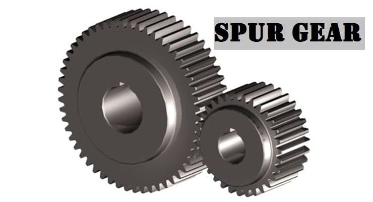
The spur gear can be internal or external. When the teeth are cut outside the cylinder. They are known as External gears and when teeth are cut on internal gears.
When External meshes they will Rotate in the opposite direction and when internal meshes they will Rotate in the same direction.
As we know there is no Axial thrust. There is one Advantage of that bearing work will be reduced. Due to the impact loading force is acting for very little time and due to this, there will be chances of fatigue failure.
Types of Spur Gear:
There are three important types of Spur Gear and those are:
- External Spur Gear
- Internal Spur Gear and
- Spur Rack and Pinion.
External Spur Gear:
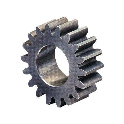
These spur gears have external teeth on the outer surface of the cylinder. When the two gear meshes both will Rotate in the opposite direction. The driver is usually smaller in size & Driven is moved in the opposite direction to the Driver.
Internal Spur Gear:
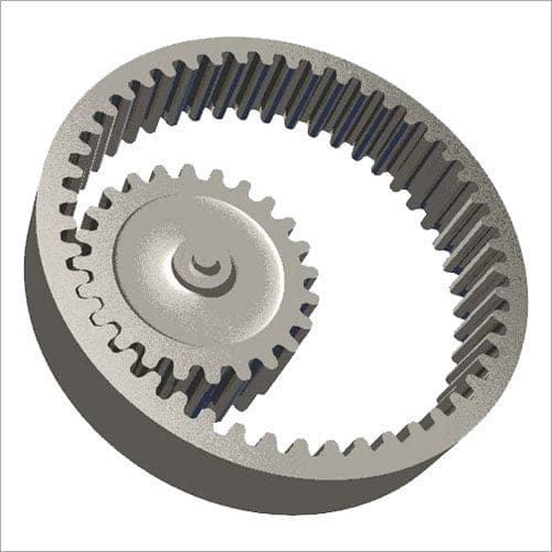
In internal spur gear, teeth are cut on the internal/inner surface. This gear will be like a ring into that pinion or smaller gear meshes inside it & the two shafts will Rotate in the same direction.
Spur Rack and Pinion:
It is a special type where pitch surface is a plane means it has an infinite diameter which is called a rack. It has also the same teeth means of the same module as that of pinion which is usually smaller.
This combination of Rack pinion is used to convert the rotary motion of pinion to translating motion of rack or translating motion of rack to rotary motion of pinion.
Rack’s pinion is commonly found in steering arrangement mechanical Advantages are less than simple spur gears but the backlash will be less between the meshing gears which will provide better power transmission.
Rack and pinion are used in actuators like in pipeline, transport rack, and Pinion are also used in railway engines to control brake.
Spur Gear Terminology:
The following spur gear terminology are:
- Pitch Cylinder
- Pitch Circle
- Pitch Diameter
- Pitch Surface
- Pitch Point
- Pitch
- Circular Pitch
- Module
- Gear Ratio
- Velocity Ratio
- Addendum Circle
- Dedendum
- Dedendum Circle
- Clearance
- Full depth
- Working Depth
- Space Width
- Tooth Thicknes
- Backlash
- Face
- Pressure line
- Arc of Contact
- Path of Contact
Let’s study one by one,
- Pitch cylinder: These are imaginary cylinder or friction cylinder which are imagined to roll together pure rolling motion transmit the motion.
- Pitch Circle: This is the circle corresponding to the pitch cylinder that is shown in a normal plane to the Axis.
- Pitch Diameter: It is the diameter of pitch circle.
- Pitch Surface: It is the surface of pitch cylinder.
- Pitch point: It is the point where the two pitch circle meets.
- Circular pitch: It is denoted by P .
- It is the distance from the corresponding point of one tooth to another tooth along the circumference of the pitch circle. It cannot be determined precisely.
P=πd/T , d=Pitch diameter . T=No. of teeths
Due to involvement of π ,It cannot measure precisely
Diametrical Pitch: It is the ratio of no. of teeth to the pitch diameter .
It is denoted by Pd = T/d
p × pd =(πd/T)×(T/d)=π
*d is measured in inches .
Diametrical Pitch is not measured in SI units.
Module: It is the ratio of the pitch diameter to the no. of teeth. pitch diameter should be in mm. m=d/t and Gears are specified According to module.
Gear Ratio: It is the ratio of no. of teeth of gears (Driver) to the no. of teeth of a pinion (driven).
Gear Ratio is denoted by G and G=T/t =Driver’s Teeth/Driven teeth
Velocity Ratio: It is the ratio of the Angular velocity of the follower (pinion) to the Angular speed of driver (gear).
For common velocity is same between the cylinder
w1r1 = w2r2 or w1d1 = w2d2
V.R = w2/w1 =d2/d1 =N2/N1
Also w = πDN/60
So w is directly proportional to RPM(N)
Both gears should have same Circular pitch to mesh together .
P=πd1/T1=πd2/T2 so, d1/d2=T1/T2
So, V.R =w2/w1=d1/d2=N1/N2=T1/T2
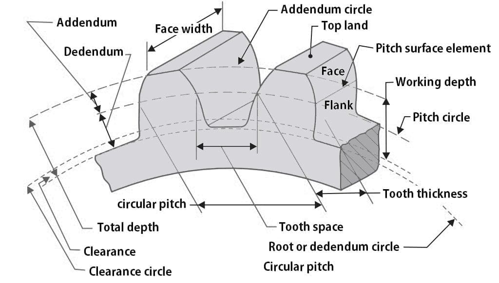
Addendum Circle: The circle touching the tip of the teeth .
Addendum: It is Radial distance of the tooth above the circle . Normally its value is equal to 1 module
Addendum = module(m)
- Dedendum Circle: It is the circle that passes through the bottom of the teeth circle are parallel to the pitch circle
- Dedendum: It is the Radial Distance measured from the pitch circle to the Roots of the teeth. Its value is generally more than Addendum. Its value is 1 .157m
- Clearance: The difference between Addendum and Dedendum Radially. Clearance=1.157m-1m = 0.157m
- Full Depth: It is the sum of Addendum and Dedendum.
- Working Depth: As we know tooths penetrates into tooth space means It is the addition of the Addendum of Driver’s Driven when meshed together.
- Space width: It is the width of tooth space along the pitch circle.
- Tooth thickness: Thickness of tooth of gear measured along the pitch circle.
- Backlash: Difference between tooth space and tooth Thickness.
- Flank: It is the surface of the tooth between the pitch circle and bottom.
- Face: It is the surface of the tooth between the top land & pitch circle.
- Pressure line: The driver exerts a force on the drive and this force will be along a line this is called a line of action.
- This is a line passing through pitch point & Between. It passes through the point of contact of the driver and driven. This is also called a common normal or pressure line. This line is important for the measurement of pressure angle.
- Pressure Angle: The angle between the common tangent to the pitch circle and the pressure line. It is called a pressure angle or angle of obliquity.
- When the pressure angle is small there will be better power transmission and Lesser pressure Exerts on the bearing.
- Path of contact: It is the locus of the point of contact from the beginning of Engagement to the end of the Engagement (CD)
- The path of contact is changing but the line of action will remain the same. It is divided into 2 parts I.e path of approach & another path of recess. Path of approach (CP) is the distance between the beginning of Engagement to the pitch point & the path of the recess (PD) is the distance between pitch point and End of Engagement.
- Arc of contact: The locus of the point on the pitch circle from the beginning of Engagement to the end of the Driver and driven meshing together is called arc of contact.
Spur Gear Advantages:
The following advantages of Spur Gear are:
- Easy to manufacture.
- No Axial thrust.
- Bearing is not needed.
- Simple compact design that makes them easy to design and install even in limited or restricted spaces.
- Constant speed Driven can be achieved we can increase or decrease According to our needs.
- Spur gears are not going to slip during the operation & they are reliable and durable.
- With less power loss, we can achieve 90-95% power efficiency.
- Less expense as compared to the other gears.
Spur Gear Disadvantages:
The disadvantages of Spur Gear are:
- Spur gears have instant contact for few seconds making them under impact stresses as the load is variable cyclic stresses comes into the picture thus the fatigue failure may occur.
- It is noisy at high speed.
- They cannot be used for long-distance power transmission.
- They can only have limited center distance.
- As the velocity increases, Vibration will increase.
- It cannot be used when Axial direction, change is required.
- Can’t use for high load.
- Not strong when used at high speed.
Spur Gear Application:
The following application or Uses of Spur Gear are:
- Conveyor system
- Speed Reducer
- Engine and Mechanical Transportation system
- Hand drill
- Gear pumps and Motors
- Machining Tools
- Marine Engines
- Power plants
- Rolling Mills
- Washing Machines
- Fuel pumps
So here we studied Spur Gear in detail. I hope you have got some overview on Spur Gear. If yes, please do share with your colleague and social platform too.




Discussion about this post