Diesel Cycle is the process of the Diesel Engine. In this article, we will look at the Definition, Process, PV, and TS Diagram, Derivation, and Efficiency [Notes with PDF] of Diesel Cycle.
So Let’s start with the definition first,
Diesel Cycle Definition:
Diesel Cycle is defined as a combustion process in which the burning of diesel fuel takes place and charge receives from the burning of diesel fuel. The diesel cycle is also known as the constant pressure cycle (pressure is constant during the heat addition process).
So this process complete in four steps: Suction, Compression, Ignition, and Exhaust.
Diesel Cycle Process:
Diesel cycle consists of four process those are:
- Suction
- Compression
- Expansion and
- Exhaust Process
Suction Process:
The suction process is the first process in which air is entered into the cylinder. The piston is at TDC Top dead center. When air is entered the piston moves TDC to BDC Bottom dead center.
During the suction process, the inlet valve is open and the exhaust valve is closed. As you can see in the diagram.
Compression Process:
The compression is the second process in which the air is entered into the cylinder will be compressed along with the fuel. The piston is at BDC Bottom dead center.
During the compression process, the inlet valve is closed and the exhaust valve is also closed. For the compression process, the piston moves to the top dead center from the bottom dead center. Here temperature and pressure increase. Go through the diagram too.
At the end of the compression process, it is having high pressure and temperate, the fuel is injected into the cylinder and thus the ignition process occurs.
Expansion Process:
It is the third process after suction and compression. In this process, the piston is at the top dead center. The piston moves the top dead center to the bottom dead center.
As we have seen at the end of the compression process the burning of fuel takes place. So it released chemical energy and that energy push the piston to the bottom dead center.
During this process both the valve (Inlet and Exhaust) are closed.
Exhaust Process:
Now, this is the final process in which the piston is at the bottom dead center. The cylinder having charges which are released to the engine through the exhaust port.
During this process inlet valve is open and exhaust valve is closed.
So This is how diesel cycle process takes place.
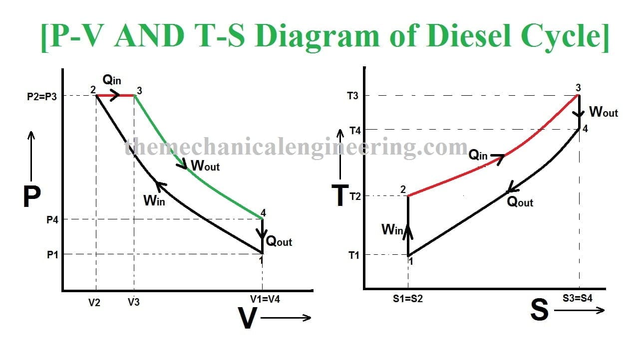
Diesel Cycle PV and TS Diagram:
Now we will study PV and TS Diagram:
- Process 1-2: Reversible Adiabatic Compression Process
- Process 2-3: Constant Pressure Heat addition
- Process 3-4: Reversible Adiabatic Expansion Process
- Process 4-1: Constant volume Heat rejection

Here we are going to study through pv and ts diagram in practical.
Process 1-2: Reversible Adiabatic Compression Process:
The cylinder contains full of air which is entered through the inlet port as we studied above. Here P1, V1, and T1 are the corresponding Pressure, Volume, and Temperature.
After the adiabatic compression process in which entropy remains constant and the air is compressed by the piston. The P2, V2, and T2 are corresponding Pressure, Volume, and Temperature after the compression process.
Process 2-3: Constant Pressure Heat addition:
Now the heat is added at a constant pressure of the system. So only temperature increases from T2 to T3 and pressure remains constant P2=P3.
And the volume varies v2 to v3.
Heat Addition formula is,
Qadd = mCp(T3-T2)
Process 3-4: Reversible Adiabatic Expansion Process:
Here in this process the fuel get expanded that means the work is being out and temperature is decreasing from point 3 to point 4. Entropy remians constant.
At point 3 there is maximum temperature and the temperature is decreasing to point 4.
Process 4-1: Constant volume Heat Rejection Process:
Here the heat is being rejected at a constant volume process that means the pressure is decreasing P4 to P1 but volume remains constant V1=V4.
Heat rejected formula is,
Qrej = mCv(T4-T1)
Diesel Cycle Derivation:
We can calculate efficiency of diesel cycle from the derivation. So lets start,
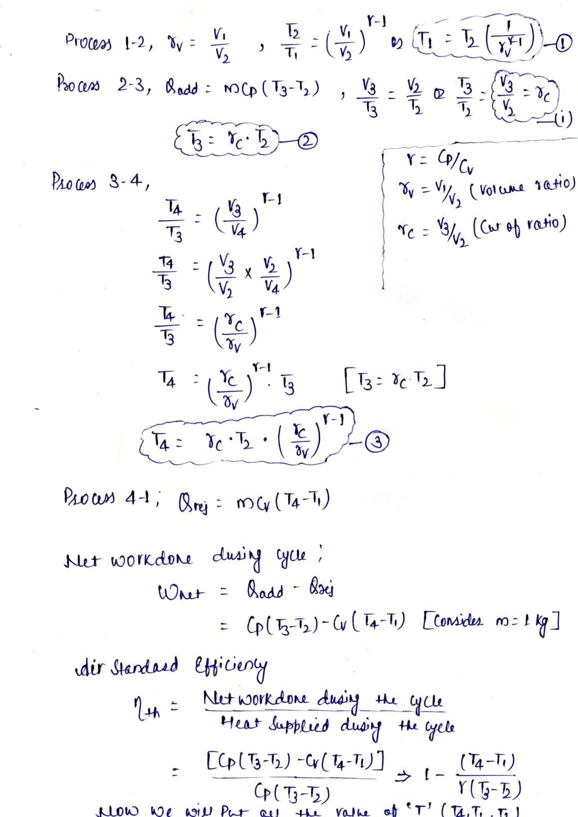
From the PV and TS Diagram the process 1 to 4 we will list some of the important terms,
So here we find out the efficiency of diesel engine.
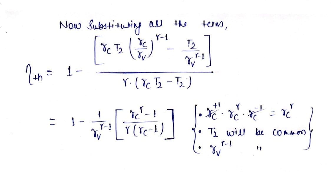
Diesel Cycle Efficiency:
The efficiency of the diesel cycle is more efficient than the Otto cycle but not more than the Carnot cycle which is having 75 Percent. The diesel cycle efficiency can be calculated from the formulas which are, (Net Work)/
(Heat supplied).
Diesel Cycle Application:
The following application of Diesel Cycle:
- Diesel Cycle is used in two-stroke and four-stroke diesel engine. The diesel cycle produces more amount of power compared with less fuel to the Otto cycle.
- The diesel engine is used in heavy vehicles like Car, Trucks, Generator, and Buses extra.
- The fuel system is larger here but where in Otto cycle has smaller.
- Diesel Engine has the lowest Specific fuel consumption.
Conclusion:
| Process | Operation Name | Piston Position |
| 1-2: | Reversible Adiabatic Compression Process. | BDC TO TDC |
| 2-3: | Constant Pressure Heat addition | BDTC TO TDC |
| 3-4: | Reversible Adiabatic Expansion Process | TDC TO BDC |
| 4-1: | Constant volume of heat rejection | BDC TO TDC |
So here we read about the Diesel Cycle in detail. If you have any query you can comment it down and If you like the effort do not forget to share it. till then Thank You so much we will meet in another article.
Internal Resources:
Difference between Otto Cycle and Diesel Cycle
Reference [External Links]:
- courses online Diesel Cycle Derivation
- Wikipedia Diesel Cycle

Discussion about this post