What is a Pneumatic System?
Pneumatics is a branch of engineering that uses wind or high-pressure air to perform certain operations. A pneumatic system is a connection of various components such as (compressors, intercoolers, controllers, and actuators), that converts the pressure energy of compressed air into mechanical work.
Pneumatic systems are used where human strength and accuracy are not enough. Nowadays Pneumatic systems are widely used in various industries to automate several processes.
It not only lifts heavy loads and increases the accuracy but it also decreases the time period to perform certain activities.
Some of the most common examples of pneumatic systems are air brakes, pneumatic arms, pneumatic cable jetting, and pneumatic shock absorbers.
History of Pneumatic System:
Humans were familiar with pneumatics and the technology behind it since long ago. A blowgun was the first pneumatic device to be made in 429AD and was used to hunt down animals in the primitive age.
In the 1st century, a Greek mathematician, Hero of Alexandria, was the first one to write about pneumatic systems and how one can generate mechanical work from the energy generated by wind or pressurized air.
Influenced by him, the German physicist Otto von Guericke invented the first vacuum pump that can be used to displace objects using the high velocity of air.
The use of pneumatic systems grew in the 1800s. In the 1900s pneumatics became an essential feature of most modern industries.
Nowadays pneumatic systems can be seen everywhere right from large jet engines to the tiny dentist equipment used to clean teeth.
Pneumatic System Components:
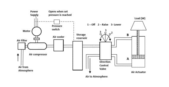
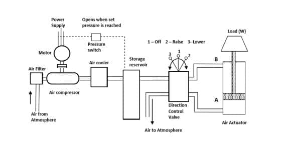
The basic block diagram of a pneumatic system is given below.
Air filter:
Air contains various impurities such as pollen grains, dust particulate, soot, etc. These impurities need to be removed from the air before it enters a pneumatic circuit.
Hence an air filter is used to restrict these impurities from entering the pneumatic circuit. The air filter is a fibrous or porous material that traps the solid particulate and allows air to move in.
It may also contain some absorbent material such as charcoal that absorbs pollutant gas particles and soot.
Air compressor:
As the name suggests the device used to compress the air is called an air compressor.
Generally, axial flow air compressors are used in pneumatic systems. These compressors have rotating blades called impellers that rotate with the help of a motor.
The impeller creates a vacuum that sucks the air via an air filter. The pressure of air at the outlet of the impeller is more than the atmospheric pressure.
The ratio of outlet pressure to the inlet pressure of the compressor is called the compression ratio. The compression ratio is different for different purposes.
Motor:
A suitable motor is used to run the compressor in a pneumatic system.
The capacity of the motor depends on the size of the compressor and the power required to run the compressor. The motor is directly connected to the power supply.
Air cooler:
Air temperature increases when the air is compressed in the compressor. This hot air is not suitable for further operation.
Hence it is important to cool down the hot air coming out of the air compressor. The cooling of air is done by an air cooler.
The main objective of an air cooler is to reduce the temperature and moisture content in the air coming out from the air compressor.
There are two types of commonly used air coolers.
- Air-cooled air cooler.
- Water-cooled air cooler.
In an air-cooled air cooler, the hot air is enclosed in pipes and cool air is forced on it with the help of a fan this cool air carries away heat from the hot air without decreasing the pressure.
While in the case of a water-cooled air cooler the heat is exchanged by indirect contact between the hot air from the compressor and cold water.
Much lower temperature can be obtained by a water-cooled air cooler than the air-cooled air-cooler. As cold water is available in large quantities, water-cooled air coolers are cost-effective and quick.
Storage reservoir:
A storage reservoir is an air pressure vessel used to store compressed air under high pressure.
This storage device ensures a smooth supply of pressurized air and eliminates fluctuations caused due to loading and unloading of air demand.
Storage reservoirs play an important role in pneumatic systems as they ensure quick response to user demand. Storage reservoirs can store both dry and wet air depending on demand.
A storage reservoir must be strong, must have high tensile strength, and must be durable. Hence the commonly used materials for storage reservoirs are Mild steel, Aluminum, Carbon steel, and Stainless steel.
Storage reservoirs have several parts. Each part is first cut down into its required dimension. These parts are then assembled by welding and bending.
FRL unit:
The full form of FRL is ‘ filter, regulator, and lubricator’ these three are generally used as one unit in a pneumatic system, but can also be used as different individual units.
FRL is an important component of a pneumatic system as it reduces losses and increases the efficiency of the system. The three basic functions of an FRL unit are as follows.
To filter out the wastewater, contaminants, and debris from the air coming out of the storage reservoir. This is done by filers and is generally the first step in an FRL unit.
The second function of the FRL unit is to regulate the pressure and restrict it from crossing the upper limit. This is done by a pressure regulator. Pressure regulation is an important step as it prevents damage to the system and also reduces unwanted losses due to high pressure.
The last stage of the FRL unit is air lubrication. In the air, lubrication is done by mixing a thin mist of oil or other lubricants into compressed air. This is generally done after filtration and regulation. This lubricated air reduces the friction between the moving parts of a pneumatic system and thus reduces the loss of energy and increases the life of the equipment.
If an FRL unit is not present in a pneumatic system it would decrease the life of the system, increase the energy consumption and reduce the efficiency of the system.
Directional control valve:
Directional control valves are the most important device used in a pneumatic system. The directional control valves or DVCs are used to control the direction and the amount of air entering the actuators.
The valves transfer the pressure energy of air to the actuators as per the command given by the operator. The generally used valve in a pneumatic system is a solenoid valve, also sometimes known as a spool valve.
These valves are operated by the action of a solenoid coil coupled with an electromagnet.
Actuators:
Actuators are devices that convert the pressure energy of fluid into mechanical movement. In the case of a pneumatic actuator the fluid used is air.
Actuators are the devices from which we get the results of pneumatic systems.
There are many types of actuators used in the industry. The actuators are classified based on the motion achieved by them.
- Linear actuators
- Single-acting cylinders
- Double-acting cylinders
- Rotary actuators
- Vane type
- Rack and pinion type
Pneumatic system Working:
The air comes into the compressor through an air filter due to the vacuum generated by the blades of the compressor
The air is filtered out in the air filter and then goes into the compressor.
The compressed air then enters the air cooler where the temperature of the air is reduced to improve the efficiency of the system.
This compressed cold air is then stored in the storage reservoir to make the air readily available.
The air then enters the FRL unit where it is filtered again, pressure is regulated and some oil is added to lubricate the air.
From the FRL unit, the air goes into the direction control valve where the air is sent according to the user’s action.
From DCV the air finally enters the actuator where the pressure energy is converted to mechanical work.
Difference between the Hydraulic System and the Pneumatic System:
| Pneumatic system | Hydraulic system |
| The pneumatic system uses air as the working fluid. | The Hydraulic system uses oil as the working fluid. |
| This is an open-loop system. | This is a closed-loop system. |
| The construction of pneumatic systems is simple. | The construction of the hydraulic system is complex. |
| The cost of a pneumatic system is low | The cost of a hydraulic system is high |
| Pressure in the system is low hence the size is small. | The system’s internal pressure is high, hence the size is bigger. |
| Accuracy is less. | Accuracy is high. |
| The air inside the system is not flammable. | The oil inside the system is flammable. |
| The system does not corrode easily. | The system corrodes easily. |
| The power to size ratio is less. | The power to size ratio is more. |
Advantages of Pneumatic System:
- The air used is infinitely available.
- The working medium is inflammable.
- It is independent of the outside temperature.
- The system is safe and tidy.
- Generates instant mechanical work.
- Corrosion problems are not severe.
Disadvantages of Pneumatic system:
- The system is noisy.
- There are often leaks in the system.
- Low power-to-weight ratio.
- Always prone to dust and contaminants.
- Suitable only for low-pressure applications.
Applications of Pneumatic System:
Pneumatic systems have an infinite number of applications in today’s modern era. Some of the main applications of pneumatic systems are.
- Automatic production lines.
- Doors of metro trains.
- Medical equipment.
- Car washing.
- Pneumatic brakes.

![Different Types of Measuring Tools and their Uses [Notes & PDF] Feature Image of Types of Measuring Tools](https://themechanicalengineering.com/wp-content/uploads/2023/01/Feature-Image-of-Types-of-Measuring-Tools-300x171.jpg)
![Steel: Properties, Different Types and Applications [Notes & PDF] Feature Image of Steel](https://themechanicalengineering.com/wp-content/uploads/2023/01/Feature-Image-of-Steel-300x168.jpg)

Discussion about this post